Table of Contents
Advertisement
Quick Links
Operating Manual
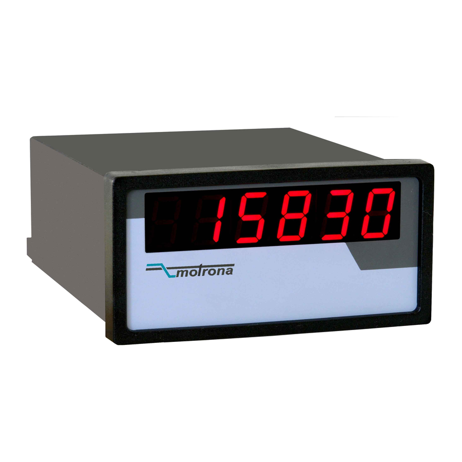
Process value and parameter indicators for CAN-Bus
Product Features:
The CA340 variant is a simple indicator unit for remote display of all actual data which
are available on the connected CAN-Bus network. Arbitrary parameters or actual values
can be read or displayed.
CA541 is a combination of preset switch and indicator. While the BCD switch allows to
make register changes via CAN-Bus, the LED display provides information about the
actual setting of the same or any other register value.
Available Devices:
CA340: Display unit only
CA541: Display / Preset combination (SDO / PDO switchable)
3046 Home Road. Powell, OH 43065
CA340 and CA541
P: (740) 917-5781
F: (740) 917-5791
www.GenesisAutomationOnline.com
www.GenesisAutomationOnline.com
Sales@GenesisAutomationOnline.com
Advertisement
Table of Contents

Related Manuals for Motrona CA340


Summary of Contents for Motrona CA340
- Page 1 Process value and parameter indicators for CAN-Bus Product Features: The CA340 variant is a simple indicator unit for remote display of all actual data which are available on the connected CAN-Bus network. Arbitrary parameters or actual values can be read or displayed.
-
Page 2: Table Of Contents
Dual language version separated in two stand-alone versions. Legal notices: All contents included in this manual are protected by the terms of use and copyrights of motrona GmbH. Any reproduction, modification, usage or publication in other electronic and printed media as well as in the internet requires prior written authorization by motrona GmbH. -
Page 3: Safety Instructions And Responsibility
1. Safety Instructions and Responsibility 1.1. General Safety Instructions This operation manual is a significant component of the unit and includes important rules and hints about the installation, function and usage. Non-observance can result in damage and/or impairment of the functions to the unit or the machine or even in injury to persons using the equipment! Please read the following instructions carefully before operating the device and observe all safety and warning instructions! Keep the manual for later use. -
Page 4: Installation
Please find all respective hints and rules on www.motrona.com/download.html --> “[General EMC Rules for Wiring, Screening and Earthing]”. 1.4. Cleaning, Maintenance and Service Notes To clean the front of the unit please use only a slightly damp (not wet!), soft cloth. -
Page 5: Allgemeines
CANopen network for communication. CA541 also allows remote setting of a single parameter. CA340 serves as pure readout unit without preset functions. Both units are built into a DIN housing and have a 6 decade, 15mm size LED-display. -
Page 6: Connections
4. Connections Screw terminals and DIL switches for setup are located on the backplane of the unit: GND G C- C+ 1 2 3 4 1 2 3 4 5 6 7 8 10...35V CAN high Power Supply CAN low GND (100R) Current consumption, depending on supply voltage: Volt... -
Page 7: Setting Of The Network Baud Rate And Sign
Both extreme ends of the CAN network must be terminated by a 120 Ohms resistor. The shield must be connected to earth potential. Schirm / Shield 120Ohms 120 Ohms CAN+ CAN- GND CAN+ CAN- GND CAN+ CAN- GND Erster Busteilnehmer Letzter Busteilnehmer First network participant Last network participant... -
Page 8: Setting Of Unit Address And Transmission Mode
Slider 4 defines the most significant digit of the front thumbwheel switches to be transmitted as a number or a sign (CA541 only): 1 2 3 1 2 3 OFF: 0...9 ON: +/- The version with a sign (option VZ000) requires slider 4 to be “ON“ at any time! 6. -
Page 9: Data Transmission By Sdo (Service Data Object)
7. Data transmission by SDO (Service Data Object) [DIL switch slider 8 = OFF] The unit requests the display value by an SDO (Service Data Object) read request and transmits the preset value (CA541 only) by an SDO write request. Within the next 2.5 sec (Timeout) a corresponding read or write response is awaited. - Page 10 The code of the register to be displayed and the code of the register to be Set are requested from register code 473 of the target unit. When transmitting on parameter channel 1 (SDO1) Subcode 3...6 is used, transmitting on parameter channel 2 (SDO2) Subcode 7...10 is used. Therefore, it is possible to display respectively to preset two different values of one target device by using two display units running on different parameter channels (Version CA34002A and later).
-
Page 11: Datenübertragung Als Prozessdaten Mit Pdo (Process Data Object)
With the CA541, Position 6 of the 8-position DIL switch selects only temporary use of transmit data in the target device (no storage to EEPROM), or continuous use even after power down (nonvolatile storage to EEPROM by setting register Code C003 “Par. Save” to 1 after transmitting the value). - Page 12 Receive PDO: Data- Data- Data- Data- Data- Data- Data- Data- Identif ier: By te 0 By te 1 By te 2 By te 3 By te 4 By te 5 By te 6 By te 7 sy nchronous: (low) 32 bit display data (high) (low) 32 bit display data...
-
Page 13: I.e. After Transmission Of The Bootup-Message. The Initial Value Of The Toggle Bit Is 0. The Toggle
(number of decimal places). However, the value will not be stored to non-volatile memory. Therefore the number of decimal places must be re-set on every power on. Node Guarding: The CA340/CA541 provides CANopen Node Guarding. By this function the master can supervise the unit and detect any device breakdown. -
Page 14: Error Messages
No read response during initialisation Error response during initialization: E 013: - wrong code E 014: - wrong Subcode E 015: - no access E 016: Initialization error 10. Dimensions 48 (CA340) 72 (CA541) Ca340_03b_oi_e.doc / Apr-16 Page 14 / 15... -
Page 15: Technical Specifications
1,5 mm² / AWG 16 Bus connection: Communication profile: DIN ISO 11898, CANopen (CiA DS301) Available EDS files: CA340.eds / CA307.eds / CA541.eds Baud Rates (selectable): 10, 20, 50, 125, 250, 500, 1000 kbit/s BCD switch (CA 541): Adjustment range: 0 ...
Need help?
Do you have a question about the CA340 and is the answer not in the manual?
Questions and answers