Motrona touchMATRIX IX350 Operating Manual

Motrona touchMATRIX IX350 Operating Manual

Ssi indicator for absolute encoders, with touchscreen and graphic display

Advertisement

Quick Links

Operating Manual
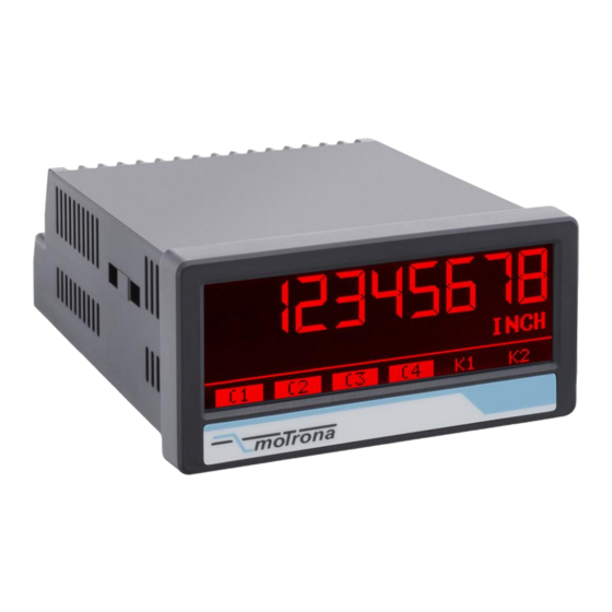
SSI indicator for absolute encoders, with touchscreen and graphic display
Product features:
Master or Slave operation with clock frequencies up to 1 MHz
For single turn and multi turn encoders with SSI formats from 10 ... 32 Bit
Bright and high-contrast display with event-dependent color variations
Emulation of a 7-segment display inclusively icons and units
Intuitive and easy parameterization by plain text and touchscreen
5 V / 24 V auxiliary output for encoder supply
Linearization with 24 control points
Numerous features, e. g. scaling, bit blanking etc.
3.78 x 1.89 inch norm panel housing and IP65 protection
Available options:
IX350:
Basic unit with SSI interface, 3 control inputs, 24 VDC encoder supply
IX355:
Basic unit like IX350, with open-circuit monitoring, 5 / 24 VDC encoder supply
Option AC:
Option AO:
Option AR:
Option CO:
Option CR:
Option RL:
Options can be combined
motrona GmbH, Zeppelinstraße 16, DE - 78244 Gottmadingen, Tel. +49 (0) 7731 9332-0, Fax +49 (0) 7731 9332-30, info@motrona.de, www.motrona.de
touchMATRIX® Indicator IX350 / IX355
Power supply 115 / 230 VAC
16 bit analog output, 4 control outputs, serial RS232 interface
16 bit analog output, 4 control outputs, serial RS485 interface
4 control outputs, serial RS232 interface
4 control outputs, serial RS485 interface
2 relay outputs

Advertisement

Table of Contents
loading
Need help?

Need help?

Do you have a question about the touchMATRIX IX350 and is the answer not in the manual?

Questions and answers

Subscribe to Our Youtube Channel

Summary of Contents for Motrona touchMATRIX IX350

  • Page 1 4 control outputs, serial RS232 interface  Option CR: 4 control outputs, serial RS485 interface  Option RL: 2 relay outputs Options can be combined motrona GmbH, Zeppelinstraße 16, DE - 78244 Gottmadingen, Tel. +49 (0) 7731 9332-0, Fax +49 (0) 7731 9332-30, info@motrona.de, www.motrona.de...
  • Page 2 Expansion of the serial interface Legal notices: All contents included in this manual are protected by the terms of use and copyrights of motrona GmbH. Any reproduction, modification, usage or publication in other electronic and printed media as well as in the internet requires prior written authorization by motrona GmbH.
  • Page 3: Table Of Contents

    Table of content 1. Safety Instructions and Responsibility................4 1.1. General Safety Instructions ......................4 1.2. Use according to the intended purpose ..................4 1.3. Installation ............................ 5 1.4. Cleaning, Maintenance and Service Notes ................. 5 2. Introduction ........................6 2.1.
  • Page 4: Safety Instructions And Responsibility

    Safety Instructions and Responsibility 1.1. General Safety Instructions This operation manual is a significant component of the unit and includes important rules and hints about the installation, function and usage. Non-observance can result in damage and/or impairment of the functions to the unit or the machine or even in injury to persons using the equipment! Please read the following instructions carefully before operating the device and observe all safety and warning instructions! Keep the manual for later use.
  • Page 5: Installation

    Please find all respective hints and rules on www.motrona.com/download.html --> “[General EMC Rules for Wiring, Screening and Earthing]”. 1.4. Cleaning, Maintenance and Service Notes To clean the front of the unit please use only a slightly damp (not wet!), soft cloth.
  • Page 6: Introduction

    Introduction The SSI display device is designed for panel mounting. It is universally applicable, with its intuitive operation, the extensive features and options. 2.1. Operation mode All functions are can be configured in the parameter menu. The device can be set to one of the following operation modes: •...
  • Page 7: Electrical Connections

    Electrical Connections The terminal screws should be tightened with a slotted screwdriver (blade width 2mm). 3.1. DC Power Supply The unit accepts DC supply from 18 to 30 V at the terminals 1 and 2. The power consumption depends on the level of the supply voltage with approx. 100 mA and the additional current required at the Auxiliary Voltage Output.
  • Page 8: Ssi-Inputs

    3.3. SSI-Inputs At Terminal 5, 6, 7 and 8, the connection is available for SSI signals. The basic settings must be set in the menu SSI PROPERTIES. Wiring for MODE Master: Wiring for MODE Slave: Ix350_02b_oi_e.doc / Mai-18 Page 8 / 50...
  • Page 9 Continuation „SSI-Inputs“: The IX355 includes an open-circuit monitoring (only with termination, e.g. 120 ohm). In slave MODE, CLK, /CLK and DATA, /DATA are monitored. In master MODE, only DATA, /DATA are monitored. Error detection /DATA DATA /CLK Status Stable data Stable data (not guaranteed), no error detection Stable data (not guaranteed), no error detection Display value freezes, no error detection...
  • Page 10: Control Inputs

    3.4 Control Inputs The three control inputs at terminal 10, 11 and 12 have HTL PNP characteristics. In the COMMAND MENU the programmable functions for the control inputs can be assigned. Available functions are: reset the display value, display switching, locking the touch screen or release the lock function of the control or relay outputs.
  • Page 11: Serial Interface (Option Ao/Ar/Co/Cr)

    3.5. Serial interface (Option AO/AR/CO/CR) A serial interface (RS232 or RS485) is available at terminal 16, 17 und 18. This interface can be configured in the SERIAL MENU. The serial interface RS232 or RS485 can be used:  for easy setup and commissioning of the units ...
  • Page 12: Ac Power Supply (Option Ac)

    Wiring of the control-outputs: 3.7. AC Power supply (Option AC) The unit accepts AC supply from 115 to 230 V at the terminals 24 and 25. The power consumption depends on the level of the supply voltage with approx. 3VA and the additional current required at the auxiliary voltage output.
  • Page 13: Display And Touch Screen

    Display and touch screen 4.1. Screen structure for parametrization The parameter menus and the parameters are described in chapter 5. Start setup procedure: To edit the parameters, press the touchscreen for 3 seconds. Menu selection: Select the parameter menu via arrow buttons and confirm with “OK”.
  • Page 14: Screen Structure In Operation

    4.2. Screen structure in operation The following displays are available during operation. Depending on the device version and the selected operating mode, only certain representations are displayed. Display with unit and status bar To switch to the next display, press the touch screen. Control - or Relay status are only shown with Option AO, CO, RL.
  • Page 15: Error Message

    4.3. Error Message ERROR: MAXIMUM DISPLAY VALUE Display value is greater than + 99,999,999 ERROR: MINIMUM DISPLAY VALUE Display value is less than-99,999,999 ERROR: SSI ERROR BIT SET The error bit of the SSI encoder is set. ERROR: SSI ENCODER FAULT Encoder error (e.g.
  • Page 16: Parameter / Overview-Menu Structure

    Parameter / Overview-Menu Structure This section provides an overview of the menus and their parameters. The menu names are printed bold and the associated parameters are listed under the menu name. Depending on the device version and the selected operation mode, only the necessary menus / parameters are shown. Menu / Parameter Menu / Parameter GENERAL MENU...
  • Page 17 Menu / Parameter Menu / Parameter PRESELECTION VALUES SERIAL MENU PRESELECTION 1 UNIT NUMBER PRESELECTION 2 SERIAL BAUD RATE PRESELECTION 3 SERIAL FORMAT PRESELECTION 4 SERIAL INIT SERIAL PROTOCOL PRESELECTION 1 MENU SERIAL TIMER MODE 1 SERIAL VALUE HYSTERESIS 1 ANALOG MENU PULSE TIME 1 OUTPUT TARGET 1...
  • Page 18: General Menu

    5.1. General Menu DISPLAY FORMAT This parameter selects the Display Format. The corresponding decimal point will be set automatically by display format 999999:59 or 9999:59:59. 99999999 Without format customization 999999:59 Display angle minutes / seconds 9999:59:59 Display in angle minutes : seconds FACTOR This parameter defines the factor.
  • Page 19 Continuation „General Menu“: SCALE UNITS This parameter defines the required engineering unit. This parameter does not affect the calculation of the display value. The number of decimal places must be defined with the parameter DECIMAL POINT. inch Default feet Stueck Grad degree Min:Sec...
  • Page 20 Continuation „General Menu“: LINEARIZATION MODE This parameter defines the linearization function. See chapter 6.1. No linearization 1 QUADRANT Linearization in the 1. quadrant 4 QUADRANT Linearization in all 4 quadrants PIN PRESELECTION This parameter defines the PIN-code to lock the quick start of the menu PRESELECTION VALUE for entering the preselection values (Master PIN 6079).
  • Page 21: Ssi Properties

    5.2. SSI Properties MODE SSI setting master mode or slave MASTER Master-Mode: Clock for SSI encoder comes from the device SLAVE Slave-Mode: Clock for SSI encoder comes from the external master. ENCODER RESOLUTION Resolution of the SSI encoder (total number of bits) Smallest value Default value Highest value...
  • Page 22 Continuation „SSI Properties“: HIGH BIT (for bit blanking) Defines the highest evaluated bit (MSB) for bit blanking. If all bits should be evaluated, HIGH BIT must be set to the given total number of bit. Smallest value Default value Highest value LOW BIT (for bit blanking)) Defines the lowest evaluated bit (MSB) for bit blanking.
  • Page 23 Continuation „SSI Properties“: ERROR BIT Defines the encoder monitoring and the error bit No error bit available. Review on connected sensor is turned off. … Position of the error bits to be evaluated Review on connected sensor is turned on. ERROR POLARITY Defined the polarity of the error bit in the case of an error Bit is low in the case of an error...
  • Page 24: Preselection Values

    5.3. Preselection Values This menu is used to set the preselection values or the switching points. The preselection values / switching points are always referred to the display value. This menu is only available for devices with option CO, AO or RL. PRESELECTION 1 Preselection / switching point 1 -99999999...
  • Page 25: Preselection 1 Menu

    5.4. Preselection 1 Menu This function is only available for devices with option CO, AO or RL. MODE 1 Switching conditions for preselection 1. Output/ relay/ display switches under the following conditions: Absolute value of the display value is greater or equal absolute value of PRESELECTION 1 With HYSTERESIS 1 not equal 0 the following switching condition is 0 |RESULT|>=|PRES|...
  • Page 26 Continuation „Preselection 1 Menu“: HYSTERESIS 1 This parameter defines the switching hysteresis of the switch-off point for preselection 1 No switching hysteresis … 99999 Switching hysteresis of 99999 PULSE TIME 1 (S) Duration of output pulse for the switching condition of preselection 1 0,000 No output pulse (static signal) …...
  • Page 27 Continuation „Preselection 1 Menu“: START UP DELAY 1 (S) Start-up suppression for the switching condition of preselection 1. Time to start the monitoring function. This adjustment is only valid for the switching condition |RESULT|<=|PRES| or RESULT<=PRES and mode SPPED and PROCESS TIME. (Start Up Delay 3 and 4 have an automatic start up suppression).
  • Page 28: Preselection 2 Menu

    5.5. Preselection 2 Menu MODE 2 Switching conditions for preselection 2., see chapter PRESELECTION 1 MENU (except the trailing value) see chapter PRESELECTION 1 MENU Trailing preselection 2: RES>=PRES- Display value is greater or equal to PRESELECTION 1 – PRESELECTION 2  ON, TRAIL PRESELECTION 2 is the trailing preselection from PRESELECTION 1.
  • Page 29: Preselection 3 Menu

    5.6. Preselection 3 Menu MODE 3 Switching conditions for preselection 3., see chapter PRESELECTION 1 MENU (except the trailing value) See chapter PRESELECTION 1 MENU Trailing preselection 3: RES>=PRES- Display value is greater or equal to PRESELECTION 4 – PRESELECTION 3  ON, TRAIL PRESELECTION 3 is the trailing preselection from PRESELECTION 4.
  • Page 30: Preselection 4 Menu

    5.7. Preselection 4 Menu If the BATCH MODE is active, the batch counter is compared with the preselection value 4. MODE 4 Switching conditions for preselection 4., see chapter PRESELECTION 1 MENU (except the trailing value) See chapter PRESELECTION 1 MENU Trailing preselection 4: 6 RES>=PRES-TRAIL Display value is greater or equal to PRESELECTION 3 –...
  • Page 31: Serial Menu

    5.8. Serial Menu This menu defines the basic settings of serial interface. This function is only available for devices with option CO or AO. UNIT NUMBER This parameter defines serial device addresses. The addresses between 11 and 99 can be assigned to the devices.
  • Page 32 Continuation „Serial Menu“: SERIAL PROTOCOL Determines the sequence of characters send, when using the serial output for cyclic data transmission under time control (xxxxxxx = value SERIAL VALUE). Setting „1“ removes the unit address from the string which allows a slight faster transmission cycle. Transmission report = Unit No., +/-, data, LF, CR Transmission report = +/-, data, LF, CR SERIAL TIMER (S)
  • Page 33: Analog Menu

    5.9. Analog Menu This menu defines the basic settings of the analog output. This function is only available for devices with option AO. ANALOG FORMAT This parameter defines the output characteristics. The analogue output is proportional to the display value. With setting ANALOG FORMAT (-10 …...
  • Page 34: Command Menu

    5.10. Command Menu INPUT 1 ACTION (function Input 1) This parameter defines the function of the input “Ctrl. In 1”. No function (d) (s) RESET/SET VALUE Transfer of the current SSI position to the SSI offset parameter FREEZE Freeze actual display value KEY LOCK disable touch screen LOCK RELEASE...
  • Page 35 Continuation „Command Menu“: INPUT 1 CONFIG This parameter defines the switching characteristics of the input “Ctrl. In 1”. ACTIVE LOW Active at „LOW“ (static) ACTIVE HIGH Active at „HIGH“ (static) RISING EDGE Activate at rising edge FALLING EDGE Activate at falling edge INPUT 2 ACTION This parameter defines the function of the input “Ctrl.
  • Page 36: Display Menu

    5.11. Display Menu Parameter changes become active only after closing the menu selection. COLOR This parameter defines the display color. Event-depending change of the display color by a switching condition is possible (see PRESELECTION 1…4 MENU) Event-depending changes are only available for devices with option CO, AO or RL. 0 RED Red display 1 GREEN...
  • Page 37: Linearization Menu

    5.12. Linearization Menu The linearization function is defined in this menu. This menu will only be showed, if the LINEARIZATION MODE in GENERAL MENU is selected. Linearization description and examples are shown in the appendix. P1(X) … P24(X) X-coordinate of the linearization point. This value representing the display value which the unit show in the display without linearization.
  • Page 38: Appendix

    Drivecom Protocol according to ISO 1745. All protocol details can be found in our manual SERPRO which is available for download from our homepage www.motrona.com. To request for a data transmission you must send the following request string to the converter:...
  • Page 39: Parameter / Serial Codes

    6.2. Parameter / serial codes Menu Name Serial Code Default GENERAL MENU DISPLAY FORMAT GENERAL MENU FACTOR -99999999 99999999 GENERAL MENU DIVIDER -99999999 99999999 GENERAL MENU ADDITIVE VALUE -99999999 99999999 GENERAL MENU DECIMAL POINT GENERAL MENU SCALE UNITS GENERAL MENU LINIARIZATION MODE GENERAL MENU PIN PRESELECTION...
  • Page 40 Continuation „Parameterliste“: Menu Name Serial Code Default PRESELECTION 2 MENU MODE 2 PRESELECTION 2 MENU HYSTERESIS 2 99999 PRESELECTION 2 MENU PULSE TIME 2 (S) 60000 PRESELECTION 2 MENU OUTPUT TARGET 2 PRESELECTION 2 MENU OUTPUT POLARITY 2 PRESELECTION 2 MENU OUTPUT LOCK 2 PRESELECTION 2 MENU START UP DELAY 2 (S)
  • Page 41 Continuation „Parameterliste“: Menu Name Serial Code Default COMMAND MENU INPUT 1 ACTION COMMAND MENU INPUT 1 CONFIG. COMMAND MENU INPUT 2 ACTION COMMAND MENU INPUT 2 CONFIG. COMMAND MENU INPUT 3 ACTION COMMAND MENU INPUT 3 CONFIG. COMMAND MENU COMMAND MENU COMMAND MENU COMMAND MENU COMMAND MENU...
  • Page 42 Continuation „Parameterliste“ Menu Name Serial Code Default LINEARIZATION MENU P15(X) -99999999 99999999 LINEARIZATION MENU P15(Y) -99999999 99999999 LINEARIZATION MENU P16(X) -99999999 99999999 LINEARIZATION MENU P16(Y) -99999999 99999999 LINEARIZATION MENU P17(X) -99999999 99999999 LINEARIZATION MENU P17(Y) -99999999 99999999 LINEARIZATION MENU P18(X) -99999999 99999999 LINEARIZATION MENU...
  • Page 43: Linearization

    6.3. Linearization The linearization function of this unit allows converting a linear input signal into a non-linear developing (or vice versa). There are 24 programmable x/y coordinates available, which can be set in any desired distance over the full conversion range. Between two coordinates, the unit uses linear interpolation.
  • Page 44 Application Example: The picture below shows a watergate where the opening is picked up by means of an incremental encoder. We would like to display the clearance of the gate "d", but the existing encoder information is proportional to the angular information φ. Ix350_02b_oi_e.doc / Mai-18 Page 44 / 50...
  • Page 45: Reading Ssi-Value

    6.4. Reading SSI-Value The received data is always filled to 32 bit data length. Ix350_02b_oi_e.doc / Mai-18 Page 45 / 50...
  • Page 46: Internal Processing And Calculation Of Ssi Data

    6.5. Internal processing and calculation of SSI data Ix350_02b_oi_e.doc / Mai-18 Page 46 / 50...
  • Page 47 Continuation „Internal processing and calculation of SSI data” Ix350_02b_oi_e.doc / Mai-18 Page 47 / 50...
  • Page 48: Dimensions

    6.6. Dimensions Ix350_02b_oi_e.doc / Mai-18 Page 48 / 50...
  • Page 49: Technical Specifications

    6.7. Technical Specifications: Technical Specifications: Connections: Connector type: screw terminal, 1.5 mm² / AWG 16 Power supply (DC): Input voltage: 18 … 30 VDC Protection circuit: reverse polarity protection Consumption: approx. 150 mA (unloaded) Fuse protection: extern: T 0.5 A Power supply (AC): Input voltage: 115 / 230 VAC (60/50 Hz)
  • Page 50 Serial interface: Format (Option A0/CO): RS232 (Option Format (Option AR/CR) RS485 AO/AR/CO/CR) Baudrate: 9600, 19200 or 38400 baud Display: Type: LCD (backlight) Display range: 8 digits plus sign (-99999999 … 999999999) Digit height 13 mm height Color: red / green / yellow (switchable) Operation: resistive touchscreen Housing:...

This manual is also suitable for:

Touchmatrix ix355

Table of Contents