Advertisement
For replacement parts visit
WENPRODUCTS.COM
Your new tool has been engineered and manufactured to WEN's highest standards for dependability,
ease of operation, and operator safety. When properly cared for, this product will supply you years
of rugged, trouble-free performance. Pay close attention to the rules for safe operation, warnings,
and cautions. If you use your tool properly and for intended purpose, you will enjoy years of safe,
reliable service.
NOTICE: Please refer to wenproducts.com for the most up-to-date instruction manual.
Plate Compactor
IMPORTANT:
NEED HELP? CONTACT US!
Have product questions? Need technical support?
Please feel free to contact us at:
800-232-1195
techsupport@wenproducts.com
WENPRODUCTS.COM
bit.ly/WENvideo
(M-F 8AM-5PM CST)
Advertisement
Table of Contents

Related Manuals for Wen 56035T


Summary of Contents for Wen 56035T
- Page 1 IMPORTANT: Your new tool has been engineered and manufactured to WEN’s highest standards for dependability, ease of operation, and operator safety. When properly cared for, this product will supply you years of rugged, trouble-free performance. Pay close attention to the rules for safe operation, warnings, and cautions.
-
Page 2: Table Of Contents
If assistance for information or service is required, please contact the Customer Service Help Line by calling 800-232-1195; customer will be asked to provide the following information when calling. Record information in the spaces provided below and make sure to save your original purchase receipt. MODEL NUMBERs: 56035, 56035T DATE OF PURCHASE: ______________________________________________ PURCHASED FROM: ______________________________________________... -
Page 3: Specifications
Ignition System Non-contact transistor Displacement 212cc Fuel Tank Capacity 1 Gallon Engine Oil Capacity 20 fl. oz (0.6 L) Spark Plug F6TC NOTE: To prevent pavers from breaking or marring, we recommend using the WEN 56035-047 Construction Zone Plate Compactor Pad. -
Page 4: Introduction
Every effort has been made to ensure the accuracy of the information in this manual. WEN reserves the right to change this product, manual and specifications at any time without notice. Please keep this manual available to all users during the entire life of the plate compactor. - Page 5 SAFETY INFORMATION For any questions regarding the hazard and safety notices listed in this manual or on the product, please call (800) 232-1195 M-F 8-5 CST before using the plate compactor. DANGER: CARBON MONOXIDE Using a plate compactor indoors CAN KILL YOU IN MINUTES. Engine exhaust contains carbon monoxide (CO).
- Page 6 20) Never use accessories or attachments that are not recommended by WEN for this model of plate compactor. 21) DO NOT add fuel to the plate compactor if it is placed on top of a plastic surface such as a pickup truck bed with a plastic liner.
-
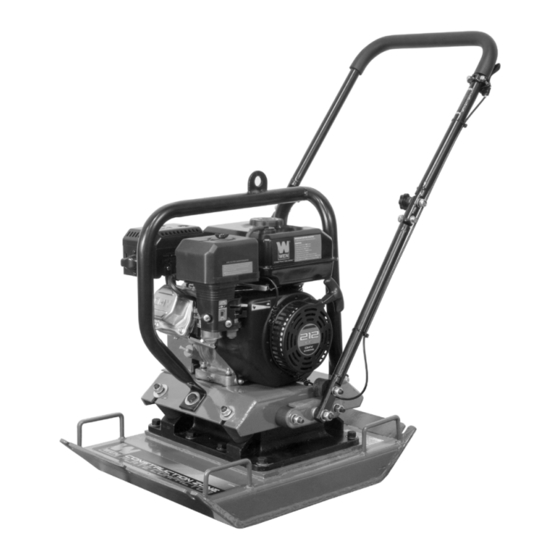
Page 7: Know Your Plate Compactor
KNOW YOUR PLATE COMPACTOR Use the illustration below to become familiar with the locations and functions of the various components and controls of this plate compactor. 1. Muffler 8. Recoil Starter Handle 2. Handle 9. Choke 3. Throttle 10. Fuel Valve 4. -
Page 8: Assembly
ASSEMBLY In order to best protect the plate compactor while in the package, this product comes with some components disassembled. Please complete the following assembly step before proceeding to use the plate compactor. If after reading this section, you are unsure about how to perform any of the steps, please call 800-232-1195 (M-F 8-5 CST) WARNING: This plate compactor is heavy. -
Page 9: Operation
PREPARATION STEP 2 - ADD GASOLINE: Use fresh (within 30 days from purchase), lead-free gasoline with a mini- mum of 87 octane rating. Do not mix oil with gasoline. 1. Make sure the plate compactor is on a level surface. Fig. - Page 10 OPERATION STARTING THE PLATE COMPACTOR: 1. Check the oil and fuel levels. 2. Turn the fuel valve to the “ON” position. 3. Move the choke lever to the “START” position. 4. Set the engine switch to the “ON” position. 5. Move throttle lever to “MIN” position. 6.
- Page 11 OPERATION Grip the handle firmly with both hands. To avoid injury, keep hands, fingers, and feet away from the compac- tor base. Grip the handle of the compactor firmly with both hands. If both hands are holding the handle and your feet are clear of the compactor base, your hands, fingers, and feet cannot be injured by the plate.
-
Page 12: Maintenance
OPERATION STOPPING THE PLATE COMPACTOR: 1. Move handle lever to “MIN” position to disengage the compactor. 2. Turn the engine switch to the “OFF” position. 3. Turn the fuel valve to the “OFF” position. FOR EMERGENCY SHUTDOWNS, move the throttle to the idle position and turn the engine switch OFF. WARNING: Allow the unit to cool for several minutes before touching areas that become hot during use. - Page 13 MAINTENANCE FILLING CRANKCASE WITH OIL: 1. Make sure the plate compactor is on a level surface. Tilting the plate com- pactor to assist in filling will cause oil to flow into engine areas and will cause damage. Keep plate compactor level! 2.
- Page 14 MAINTENANCE AIR CLEANER MAINTENANCE: Routine maintenance of the air cleaner helps maintain proper air flow to the carburetor. Check that the air cleaner is free of excessive dirt. 1. Remove air cleaner cover (Fig. 9 - 1). Remove both elements and inspect them for holes or tears.
- Page 15 MAINTENANCE DRAINING THE FUEL TANK: Clean the fuel tank each year or before storing the plate compactor for extended periods of time. To drain the fuel tank and carburetor: 1. Turn the fuel valve to the “OFF” position (Fig. 13 - 1). 2.
- Page 16 MAINTENANCE STORING THE PLATE COMPACTOR: If the unit is being stored for short periods of time (30 to 60 days), then when taking the unit out of storage, add gasoline and fuel stabilizer in the proper ratio to the tank until the tank is full. NOTE: Filling the tank reduces the amount of air in the tank and helps reduce deterioration of fuel.
-
Page 17: Troubleshooting
TROUBLESHOOTING IMPORTANT: If trouble persists, please email techsupport@wenproducts.com or call our customer help line at (800) 232-1195 M-F 8-5 Central Time. PROBLEM CAUSE SOLUTION Engine switch is set to “OFF.” Set engine switch to “ON.” Fuel valve is turned to “OFF.” Turn the fuel valve to the “ON”... -
Page 18: Exploded View And Parts List
EXPLODED VIEW AND PARTS LIST (VIBRATOR ASSEMBLY) - Page 19 EXPLODED VIEW AND PARTS LIST (VIBRATOR ASSEMBLY) Part Number Description Specification Qty. 56035-G-001 Eccentric Block 56035-G-002 Oil Seal 28 x 50 x 10 56035-G-003 Bearing Cover 56035-G-004 Bearing 6306 56035-G-005 Bearing Seat 56035-G-006 6 x 6 x 20 56035-G-007 Main Shaft 56035-G-008 Inner Hexagon Bolt M6 x 16...
- Page 20 EXPLODED VIEW AND PARTS LIST (PLATE COMPACTOR)
- Page 21 EXPLODED VIEW AND PARTS LIST (PLATE COMPACTOR) Part Number Description Specification Qty. 56035-E-000 Engine 56035-147 5*40 56035-020 Pulley 56035-019 Washer M8×30×6 56035-018 Spring Washer Ø 8 56035-017 Hex Bolt M8*30 56035-005-3 Washer Ø 10 56035-048 Handle Fixed Plate 56035-049 Handle Rubber Damper 56035-050 Locked Nut 56035-005L...
- Page 22 EXPLODED VIEW AND PARTS LIST (ENGINE) NOTE: The entire engine is available as a single assembly under model number 56035-E-000. Fig. 2 - Crankcase Assembly Fig. 1 - Cylinder Head Assembly Part Description Qty. Part Description Qty. Crankcase Cylinder Head Fig.
- Page 23 EXPLODED VIEW AND PARTS LIST (ENGINE) Fig. 5. Piston Ring/Connecting Rod Part Description Qty. Piston Ring Fig. 5 - 1 P54105 Assembly Fig. 5 - 2 P54106 Piston Ring Clip Fig. 4 - Crankshaft Fig. 5 - 3 P54109 Piston Part Description Qty.
- Page 24 EXPLODED VIEW AND PARTS LIST (ENGINE) Fig. 9 - Carburetor Assembly Fig. 8 - Shroud Part Description Qty. Part Description Qty. Carburetor Fig. 9 - 1 56035-E-067 Assembly Fig. 8 - 1 P54668 Shroud Air Cleaner Cylinder Body Fig. 9 - 2 56035-E-068 Fig.
- Page 25 EXPLODED VIEW AND PARTS LIST (ENGINE) Fig. 13 - Flywheel/Impeller Part Description Qty. Fig. 13 - 1 P54630 Flywheel Nut Fig. 12 - Gas Tank Fig. 13 - 2 56035-E-087 Starter Pulley Part Description Qty. Fig. 13 - 3 P54634 Impeller Fig.
-
Page 26: Warranty Statement
WEN® will repair or replace, at its discretion, any part that is proven to be defective in materials or workman- ship under normal use during the two (2) years warranty period. Warranty repairs or replacements will be made without charge for parts or labor.
Need help?
Do you have a question about the 56035T and is the answer not in the manual?
Questions and answers
What is the valve clearance on the 56035-e-000 Honda engine