Table of Contents
Advertisement
Advertisement
Table of Contents

Related Manuals for Keithley 2281S Series


Summary of Contents for Keithley 2281S Series
- Page 1 Series 2281S Precision DC Power Supply and Battery Simulator Quick Start Guide...
-
Page 2: Safety Precautions
For maximum safety, do not touch the product, test cables, or any other instruments while Keithley products are designed for use with electrical signals that are measurement, control, power is applied to the circuit under test. ALWAYS remove power from the entire test system... - Page 3 If you are using a test fi xture, keep the lid closed while power is applied to the device under test. Keithley. Standard fuses with applicable national safety approvals may be used if the rating and Safe operation requires the use of a lid interlock.
-
Page 4: Power And Environmental Specifications
Power and environmental specifications For indoor use only. 100 V AC/120 V AC/220 V AC/240 V AC, Power supply CAUTION 50 Hz or 60 Hz Carefully consider and configure the appropriate Maximum 2000 m (6562 ft ) above sea level Operating altitude output‑off state, source levels, and compliance levels before connecting the instrument to a device that can... - Page 5 Introduction The Keithley Instruments Model 2281S Precision DC Power Model Number Description Supply and Battery Simulator is a is a highly-sensitive, 2281S-20-6 Precision DC Power Supply and Battery accurate, programmable power supply that sources stable Simulator, 20 V, 6 A low-noise voltage and monitors load currents over a wide dynamic range, from amperes to nanoamperes.
-
Page 6: Unpack And Inspect The Instrument
2. Series 2281S Quick Start Guide (this document) CAUTION 3. LAN crossover cable for ethernet Do not lift the Series 2281S using the front bezel. Lifting 4. Keithley Instruments Safety Precautions the instrument by the front bezel can cause instrument 5. Rear-panel mating connector with cover damage. -
Page 7: Connect The Instrument
, or 60 VDC for equipment rated for dry from accidentally removing a connection by hand and peak locations. Keithley Instruments products are only rated for exposing hazardous voltages. Use high-reliability fail-safe dry locations. interlock switches to disconnect power sources when a test fixture cover is opened. -
Page 8: Install The Instrument
• Where possible, use automatic handlers so operators Do not cover the ventilation holes on the top, sides, or are not required to access the DUT or other potentially bottom of the instrument. hazardous areas. Make sure the instrument is positioned so that it is easy to •... - Page 9 WARNING The power cord supplied with the Series 2281 contains a separate protective earth (safety ground) wire for use with grounded outlets. When proper connections are made, the instrument chassis is connected to power- line ground through the ground wire in the power cord. In addition, a redundant protective earth connection is provided through a screw on the rear panel.
-
Page 10: Connections For Testing
Connections for testing Two-wire connection Two-wire connections are used for basic operation when Use the wire ratings listed in the following table when making maximum accuracy is not required. Keep the wire as short connections to the instrument. as possible to reduce lead inductance and noise pickup. The following illustration shows two-wire (local sensing) DUT Usage Specifications... - Page 11 The following illustration shows two-wire (local sensing) DUT After making the connections, slide the cover over the connections to the rear panel. rear-panel mating connector and wires. NOTE WARNING When making two-wire connections with the Series 2281S, Failure to install the cable housing may result in you must short both Output Hi and Sense Hi and Output Lo personal injury or death due to electric shock.
-
Page 12: Four-Wire Remote Sense Connection
Four-wire remote sense connection After making the connections, slide the cover over the Using four-wire remote sensing connections ensures that the programmed voltage is applied to the load and compensates rear-panel mating connector and wires. for the voltage drop in the leads between the power supply and the load. -
Page 13: Overview Of The Front-Panel Options
Overview of the front-panel options ENTER and EXIT keys The ENTER key selects a highlighted option. In most cases, it opens the menu or dialog box that allows you to change settings for that option. The EXIT key returns to the previous menu or closes a dialog box. -
Page 14: Front-Panel User Interface Overview
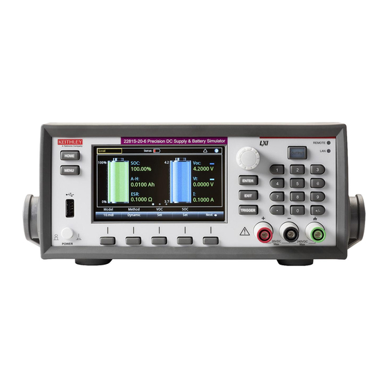
Front-panel user interface overview As you can see from the figure, the 2281S has three The front-panel user interface gives you quick access to functions: source settings, measure settings, system configuration, instrument status, reading buffer information, and other High-precision power supply: Supplies 20 V, 6 ADC •... -
Page 15: Home Screen Overview
Home screen overview The top row on the Home screen displays the status and The Home screen is the first screen that opens on power up. event indicators. You can select these options to open dialog You can always return to the Home screen by pressing the boxes that provide additional information about the status or HOME key. - Page 16 Home screen for the battery test function The top row on the Home screen displays the status and event indicators. You can select these options to open dialog boxes that provide additional information about the status or event. The OUTPUT view area of the Home screen displays the values of the battery under test.
- Page 17 Home screen for the battery simulator function The OUTPUT view area of the Home screen displays the values and status of the battery simulator. The soft-key area is located on the bottom of the Home screen. It shows the present setting values. You can change these values by selecting the buttons below the screen.
-
Page 18: Menu Screen Overview
Menu screen overview The menu items are organized under headings at the top When you press the MENU key on the front panel, the menu of the menu screen. Select an icon to access additional screen is displayed. settings. These menus allow you to choose options to set up your instrument for your applications. -
Page 19: Voltage Output And Current Measurement
Voltage output and current measurement The following example demonstrates how to configure voltage output and make a precision voltage and current When the output is turned on, changing the value with measurement using the default instrument configuration. the navigation control can source voltage and current Connect the DUT (for this example, a 1 kΩ... - Page 20 Select a measure function Specify a measurement range The Series 2281 allows you to perform the following You can set ranges for the measurement values in the power measurement functions. supply function. You can set specific ranges or allow the Measure functions What the instrument measures instrument to choose the ranges automatically.
-
Page 21: Application Examples
Application examples To set the ranges from the power supply Home screen: 1. Press the HOME key and select the Range soft key. The Battery test Range dialog box is displayed. 2. Use the up and down arrow soft keys to select the range. The following example demonstrates how to conduct a The Home page is updated with the new range setting. - Page 22 The battery under test and the Model 2281S-20-6 can To test a battery and generate a battery model: be connected by two-wire sense connections. However, 1. Select the battery test function on the startup screen. four-wire sense connections, as shown in the following 2.
- Page 23 7. Under Measure, select A-H/C. Starting from this step, the 14. After the charging is finished, select Generate in the soft 2281S charges the battery, measures its capacity, and key Measure AH area to generate a battery model. generates a battery model. 15.
-
Page 24: Battery Simulation Test
Battery simulation test The following example demonstrates simulating a battery with Model 2281S-20-6. This example shows how to use a 2281S to replace a real battery so you can power your device and test the device in different battery states more efficiently. Equipment required: •... - Page 25 To simulate a battery with 2281S-20-6 using the front panel: 8. Select I-Limit in soft key area 2 and set the current limit. 1. Select the battery simulator function on the startup screen. The maximum current from the 2281S to the DUT cannot be set higher than 6.1 A.
-
Page 26: Next Steps
Precision DC Power Supply and Battery Simulator Reference Manual, which provides detailed information about all of the features of the instrument. Also see the Keithley Instruments website, tek.com/keithley for support and additional information about the instrument. FAQs and next steps... -
Page 27: Contact Information
Contact information: Middle East, Asia, and North Africa Find more valuable resources at TEK.COM Australia* 1 800 709 465 Copyright © 2019, Tektronix. All rights reserved. +41 52 675 3777 Austria 00800 2255 4835 Tektronix products are covered by U.S. and The Netherlands* 00800 2255 4835 foreign patents, issued and pending.
Need help?
Do you have a question about the 2281S Series and is the answer not in the manual?
Questions and answers