Table of Contents
Advertisement
Quick Links
E41•T41 SERIES
Pump Manual
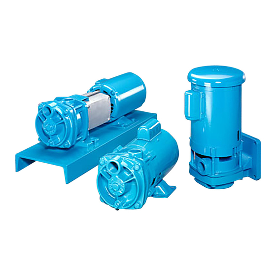
HORIZONTAL CLOSE COUPLED
VERTICAL FLANGE MOUNTED
FLEXIBLE COUPLED
Distributed in the UK by.....
Pump Engineering Limited. Unit B1, Riverside Industrial Estate,
Littlehampton, West Sussex, BN17 5DF, United Kingdom
Tel: 01903 730900
email: sales@pumpeng.co.uk Web: www.pumpeng.co.uk
Fax: 01903 730234
Section E41•T41 Page 501
Dated June 2016
97-4622-01-588
Advertisement
Table of Contents

Related Manuals for MTH PUMPS T41 Series


Summary of Contents for MTH PUMPS T41 Series
- Page 1 Section E41•T41 Page 501 Dated June 2016 97-4622-01-588 E41•T41 SERIES Pump Manual HORIZONTAL CLOSE COUPLED VERTICAL FLANGE MOUNTED FLEXIBLE COUPLED Distributed in the UK by..Pump Engineering Limited. Unit B1, Riverside Industrial Estate, Littlehampton, West Sussex, BN17 5DF, United Kingdom...
-
Page 2: General Instructions
Section E41•T41 Page 502 Dated June 2016 E41•T41 SERIES 97-4622-01-588 1.General Instructions HORIZONTAL CLOSE COUPLED PUMPS VERTICAL FLANGE MOUNTED CLOSE COUPLED PUMPS FLEXIBLE COUPLED PUMPS A. Inspection of Equipment and proper care must be taken to manufacturer’s instructions for con- B. - Page 3 Section E41•T41 Page 503 Dated June 2016 97-4622-01-588 the fluid source. It should be the “net positive suction head” above then drain the inlet and outlet lines. same size as the pump inlet or sized the vapor pressure of the pumped Carefully blow out the pump with based on reasonable fluid friction liquid available at the centerline...
-
Page 4: Installation
Section E41•T41 Page 504 Dated June 2016 E41•T41 SERIES 97-4622-01-588 Installation FLEXIBLE COUPLED PUMPS ticularly when lifting devices will be 1. Place the unit in position. CLOSE COUPLED PUMPS used for heavier assemblies. 2. Disconnect the coupling halves. A. Location... - Page 5 Section E41•T41 Page 505 Dated June 2016 97-4622-01-588 2E Piping the alignment. Complete the fol- 1. Using a micrometer or caliper, 2E1 Alignment lowing steps after the unit has been measure from the outside of one placed on the foundation and leveled. flange to the outside of the other It is important that all piping be lined at intervals around the periphery...
-
Page 6: Operation
Section E41•T41 Page 506 Dated June 2016 E41•T41 SERIES 97-4622-01-588 3.Operation FLEXIBLE COUPLED PUMPS 3B Inlet and Outlet Locations pumps from the factory are tested CLOSE COUPLED PUMPS (Refer to Figure 3-1) using rust inhibitors to help preclude The pump inlet is located on the this possibility. - Page 7 Without lubrication, seal faces can be service. damaged from heat buildup. E41•T41 SERIES 4.Service PUMP ENDS 4B — Disassembly of the C3 and P3 To disassemble the pump: Units (3 hp and under) A.
- Page 8 Section E41•T41 Page 508 Dated June 2016 97-4622-01-588 a. Insert the blades of the screw- drivers between the spring holder on the rotating element and the shoulder of the shaft sleeve. b. Holding the screwdrivers at approximately 3 o’clock and 9 o’clock, push the handles in Figure 4-3 toward the motor body, using...
- Page 9 Section E41•T41 Page 509 Dated June 2016 97-4622-01-588 d. Care must be taken with tapping on the end of the shaft be taken not to damage the hub the seats. They are often a sleeve with a mallet. Leave the or motor shaft.
- Page 10 Section E41•T41 Page 510 Dated June 2016 97-4622-01-588 4. Snap ring pliers. to move the rotating element carbons and seat wearing surfaces. 5. Penetrating oil. high enough to be removed by 6. 1” wood dowel (Approx. 6” long.) hand. Using tools on the rotating Cleanliness is imperative when work- 7.
- Page 11 Section E41•T41 Page 511 Dated June 2016 97-4622-01-588 install two of the thru bolts into bracket. Check for adequate the motor face to temporarily running clearance between the hold the motor bracket in place. lock collar and the motor and the lock collar and the pump.
- Page 12 Section E41•T41 Page 512 Dated June 2016 97-4622-01-588 4G Reassembly (T41- C15 and P15) d. If the impeller does not fit, 3. Install the sleeve hub and rotating repeat steps a. and b. to deter- All parts should be visually inspected element as a unit.
- Page 13 Section E41•T41 Page 513 Dated June 2016 97-4622-01-588 cavity of the motor bracket. Thumb pressure is usually sufficient to install the seat. 2. Install the motor bracket. This is best done with the motor standing on end. Make sure that both the face of the motor and the feet of Figure 4-14 the motor bracket are clean.
- Page 14 6. Under pressure, the impeller will service. 2. Connect all piping and fill the find its “hydraulic” balance. pump with fluid . E41•T41 SERIES 4.Service T41 BEARING PEDESTALS 2. Unbolt the pump from the base Exploded views of each unit, Figures and remove.
- Page 15 Section E41•T41 Page 515 Dated June 2016 97-4622-01-588 3. Repeat step 2 to remove the other 6. Using the arbor press, remove the bearing. Good support used on two (2) bearings from the shaft. the inner races will prevent bear- Refer to Figure 4-21.
- Page 16 Section E41•T41 Page 516 Dated June 2016 97-4622-01-588 4E Testing and Final Adjustments ready for pump and motor instal- lation. 1. Check to be sure that the rotating assembly turns freely. Turn the *Alternate bearing installation shaft by hand. If it is tight or rough procedures.
-
Page 17: Troubleshooting
Section E41•T41 Page 517 Dated June 2016 E41•T41 SERIES 97-4622-01-588 Troubleshooting FLEXIBLE COUPLED PUMPS 5B Reduced Capacity 9. Excessive wear — If a pump had CLOSE COUPLED PUMPS 1. Pump not up to speed — Use a previously performed satisfacto-... - Page 18 Section E41•T41 Page 518 Dated June 2016 97-4622-01-588 5E Excessive Power Consumption 4. Mechanical damage — If me- 2. Improperly installed seat or 1. Speed too high — Check RPM chanical damage is suspected, rotating element — If a seal has with tachometer.
-
Page 19: Parts And Repair Services
Refer to the MTH Pumps Limited Warranty statement. Return authorization must be obtained prior to returning any equipment. -
Page 20: Limited Warranty
Section E41•T41 Page 520 Dated June 2016 E41•T41 SERIES 97-4622-01-588 7.Limited Warranty MTH makes good faith recommendations of Products, based on its experience and the application information provided by the Purchaser. However, the responsibility for testing and approving a Product to be used for a particular purpose lies with the Purchaser.
Need help?
Do you have a question about the T41 Series and is the answer not in the manual?
Questions and answers