Advertisement
T51 • E51 SERIES
Pump Manual
HORIZONTAL CLOSE COUPLED PUMPS
VERTICAL FLANGE MOUNTED CLOSE COUPLED PUMPS
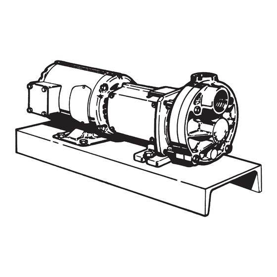
FLEXIBLE COUPLED PUMPS
Distributed in the UK by.....
Pump Engineering Limited. Unit B1, Riverside Industrial Estate,
Littlehampton, West Sussex, BN17 5DF, United Kingdom
Tel: 01903 730900
email: sales@pumpeng.co.uk Web: www.pumpeng.co.uk
Fax: 01903 730234
Section T51 • E51 Page 501
Dated February 2014
97-4623-01-588
Advertisement
Table of Contents

Related Manuals for MTH PUMPS E51 SERIES


Summary of Contents for MTH PUMPS E51 SERIES
- Page 1 Section T51 • E51 Page 501 Dated February 2014 97-4623-01-588 T51 • E51 SERIES Pump Manual HORIZONTAL CLOSE COUPLED PUMPS VERTICAL FLANGE MOUNTED CLOSE COUPLED PUMPS FLEXIBLE COUPLED PUMPS Distributed in the UK by..Pump Engineering Limited. Unit B1, Riverside Industrial Estate,...
-
Page 2: General Instructions
Section T51 • E51 Page 502 Dated February 2014 T51 • E51 SERIES General Instructions 1D Application Considerations HORIZONTAL CLOSE COUPLED be necessary to cover the pump’s 1D1 Electrical Wiring PUMPS exterior surface with oil or other rust VERTICAL FLANGE MOUNTED inhibiting coating. - Page 3 Section T51 • E51 Page 503 Dated February 2014 1D7 Freezing pump inlet is even slightly higher than By definition, NPSH means: “net the fluid source. It should be the positive suction head” above the When ambient temperatures drop same size as the pump inlet or sized vapor pressure of the pumped below the freezing point of the fluid based on reasonable fluid friction...
-
Page 4: Installation
Section T51 • E51 Page 504 Dated February 2014 T51 • E51 SERIES Installation FLEXIBLE COUPLED PUMPS embed the edges. It is unnecessary 2. Disconnect the coupling halves. CLOSE COUPLED PUMPS to completely fill under the baseplate. Do not reconnect until all align-... - Page 5 The standard coupling supplied by 1. Using a micrometer or caliper, After approximately two weeks of op- MTH Pumps has an elastomer mem- measure from the outside of one eration, check the alignment again to ber between two internal serrated...
-
Page 6: Operation
Section T51 • E51 Page 506 Dated February 2014 T51 • E51 SERIES Operation FLEXIBLE COUPLED PUMPS 3B Inlet and Outlet Locations Regenerative may cause damage. CLOSE COUPLED PUMPS (Refer to Figure 3-1) turbine pumps will typically use extra power for a period until they run in. - Page 7 Once MTH pumps allowing priming when There are no check valves or priming loosened, this material is quickly a vacuum pump or foot valve is not...
- Page 8 Section T51 • E51 Page 508 Dated February 2014 T51 • E51 SERIES Service PUMP ENDS 4B Disassembly (C3 and P3) ing the sleeve too hard could damage the seat or rotating ele- A. Preliminary The following tools and equipment ment.
- Page 9 Section T51 • E51 Page 509 Dated February 2014 d. Care must be taken with the seats. They are often a brittle material and are prone to breakage. It is recommended that a new replacement seat be installed during reassem- bly.
- Page 10 Section T51 • E51 Page 510 Dated February 2014 that a new replacement seat cedure usually does not require d. Slide the motor bracket straight be installed during reassem- excessive force. Care should off. Do not attempt to remove be taken not to damage the hub the motor bracket without first bly.
- Page 11 Section T51 • E51 Page 511 Dated February 2014 3. Remove the cover. In some removing the impeller, the impeller cases light tapping with a plastic key (#23) needs to be removed or wooden mallet on the outside from the shaft keyway. diameter of the cover may be required to loosen it from the 5.
- Page 12 Section T51 • E51 Page 512 Dated February 2014 4F Reassembly (C3 and P3) cracks and nicks. Scratches that d. Install the four (4) “O” rings (#8) might be ignored elsewhere can on the two studs. This will help produce leakage if they are on seal All parts should be visually inspected hold the bracket in place during carbons and seat wearing surfaces.
- Page 13 Section T51 • E51 Page 513 Dated February 2014 is 1/32” to 1/16” below the impeller wearing surface of c. The impeller hub should be the motor bracket. Check for facing out away from the motor adequate running clearance bracket. Refer to Figure 4-4 between the lock collar and the and 4-5.
- Page 14 Section T51 • E51 Page 514 Dated February 2014 1. The stationary seat (#125) must assembly from the spring and k. Tighten the nut as far as pos- be installed in the motor bracket install it on the motor shaft. sible by hand.
- Page 15 Section T51 • E51 Page 515 Dated February 2014 4I Testing and Final Adjustment 1. The seal seat (#125) must be 4. Compress and hold the seal installed in the motor bracket (#1) spring slightly below the snap ring before the bracket is installed on groove and install the snap ring The pump is now ready for installa- the motor.
- Page 16 Section T51 • E51 Page 516 Dated February 2014 T51 • E51 SERIES 4.Service BEARING PEDESTALS 1. Remove the flinger (#21) located in the pump end of the bearing A. Preliminary pedestal (#3). B. Disassembly C. Inspection of Components 2. Using a snap ring plier, remove D.
- Page 17 Section T51 • E51 Page 517 Dated February 2014 Figure 4-23 must seat against the shoulder for Figure 4-24 proper alignment. Refer to Figure Figure 4-25 ready for pump and motor instal- 4-23. *Also refer to Alternate 4E Testing and Final Adjustments lation.
-
Page 18: Troubleshooting
Section T51 • E51 Page 518 Dated February 2014 T51 • E51 SERIES Troubleshooting FLEXIBLE COUPLED PUMPS 2. Excessive suction lift — Relocate determine if air is being drawn in. CLOSE COUPLED PUMPS pump, supply tank or both to mini-... -
Page 19: Parts And Repair Services
In the event that it is necessary to return prior to returning any equipment. contacting MTH Pumps at 401 W. Main the pump to the factory for repairs, 6D Motors, Mechanical Seals, and St. -
Page 20: Limited Warranty
Warranty service, as well as T51 • E51 SERIES 7.Limited Warranty MTH makes good faith recommendations of Products, based on its experience and the application information provided by the Purchaser. However, the responsibility for testing and approving a Product to be used for a particular purpose lies with the Purchaser.
Need help?
Do you have a question about the E51 SERIES and is the answer not in the manual?
Questions and answers