
Related Manuals for Nordmann Engineering SBC


Summary of Contents for Nordmann Engineering SBC
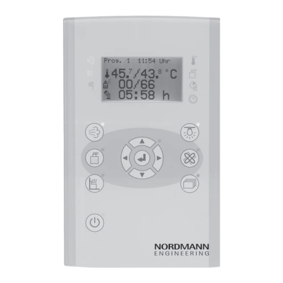
- Page 1 NORDMANN E N G I N E E R I N G Nordmann SBC Steam bath control INSTALLATION AND OPERATING INSTRUCTIONS 2557030 EN 1501...
-
Page 3: Table Of Contents
Contents General Information Information on the installation and operating manual Explanations of symbols Liability limitation Copyright Scope of delivery Spare parts Customer service Safety Intended use Request for public steambaths 2.3 Modifications and alterations Demands on technical personnel Operational safety and special dangers Identification Type plate Technical data... -
Page 4: General Information
General Information Information on the installation and operating manual An operating manual as well as an installation and operating manual are available for the NORDMANN steam bath control. The operating manual is meant for the user and gives important instructions for handling the NORDMANN steam bath control. The installation and operating manual describes the assembly, installation, commissioning, rectification of defects and repair and is provided exclusively for the technical personnel. -
Page 5: Explanations Of Symbols
Explanations of symbols Identifications of Warnings Warnings in this installation and operating manual are indicated through symbols. The instructions are introduced through signal words, which ex- press the degree of danger. Adhere strictly to the instructions and be careful to avoid accidents, personal injuries and property damage. -
Page 6: Copyright
Guarantee The guarantee period of the manufacturer starts from the time of dispatch by the manufacturer and is valid for 24 months. The delivery date can be determined from the device number on the nameplate. The manufacturer assumes no liability for any other guarantee commitments deviating from this regulation. -
Page 7: Customer Service
1.7 Customer service Your dealer or the installer of the steam bath unit can provide technical information on request. The address you can find on the invoice, delivery note or the back page of this manual. NOTE! For quick processing, before calling note down the data on the nameplate as well as the model, serial number, version etc. -
Page 8: Safety
Safety Intended use All NORDMANN steam bath controls are exclusively meant for operation and control of steam bath cabins. The control devices are permitted for domestic and commercial application. WARNING! Danger if not used correctly Any improper use of the steam bath control can lead to dangerous situ- ations. -
Page 9: Demands On Technical Personnel
Demands on technical personnel The assembly, installation, commissioning as well as rectification of defects and repairs must be carried out by qualified persons only unless otherwise mentioned. Inadequate Qualification WARNING! Danger of injury due to inadequate qualification! Improper handling can lead to significant personal injuries and material damage. -
Page 10: Operational Safety And Special Dangers
Operational safety and special dangers Pay attention to the safety and warning notes in the following chapters of this manual to minimize health hazards and to avoid dangerous situations. The following instructions are to be adhered to for your own safety and the safety of the unit: DANGER! Danger to life due to electric potential! Contact with live components can be fatal. -
Page 11: Identification
Identification Type plate The type plate is located on the control unit on the left side: RoHS conform Fig.1: control unit type plate Type designation Company logo Article number Voltage and max. power Device number Barcode Article number Barcode Article number VDE mark (for devices that are approved by VDE) RoHS marking CE mark... -
Page 12: Technical Data
Technical data General information Designation Dimensions steam bath 247 mm x 285 mm x 86,5 mm control “compact” (Height x Width x Depth) Dimensions operating 197,5 mm x 122,5 mm x 35 mm element “design” (Height x Width x Depth) Max. distance between 100 m basic device to operating element... -
Page 13: Cables
Cables Use of inappropriate cables – Electric potential DANGER! Danger to life due to electric potential! Use of inappropriate cables can lead to short circuits and subsequent fires. Damage to the insulation can be dangerous to life. Therefore: – All the cables, which lead to the steam bath, must be designed for at least 150 °C. -
Page 14: Voltage And Switching Capacity - Electrical Load
Voltage and switching capacity - electrical load Designation Switching capacity Nominal voltage 230 V 1 N ~ 50Hz Seat heating 230 V~ max. 2 kW Supply fan (steam) 230 V~ max. 60 W Supply fan (permanent) Exhaust fan 230 V~ max. 120 W Cabin light 230 V~ max. 120 W Cleaning light 230 V~ max. -
Page 15: Light And Blower
Light and blower ATTENTION! Light and blower: At the dimmable outputs of light and blower, only 230V appliances or, for low voltage, only ferrite core transformers or electronic transformers suitable for phase cutting may be used. Electronic transformers for phase cutting control may not be connected. 4.4.1 Deactivate phase cutting of light and/or blower DANGER! -
Page 16: Goods Receipt, Transport And Storage
Goods receipt, Transport and Storage Safety Inappropriate Transport ATTENTION! Damage to the control due to inappropriate transport! The control is a highly sensitive electronic device. It can get damaged due to inappropriate transport. Therefore: Remove the packing only just before starting the installation Goods receipt After the receipt the consignment should be immediately checked for any transport damages. -
Page 17: Installation
Installation 6.1 Protect against ESD CAUTION! Protect against ESD! In order to protect against ESD, do not touch any electrically conductive parts and when assembling the circuit board, only touch the plastic hous- ing or the edge from the side! Similarly, only touch the cable that connects to the board at the connector, without touching the contact surfaces. -
Page 18: Mounting The Operating Panel "Design
6.3 Mounting the operating panel “Design” The operating control can be installed maximum 100 m away from the basic control device. Installation opening of operating panel “Design” Overall width 124 mm Steam bath exterior Housing trough Installation opening for wall min. 12 mm the housing trough 106 mm 70 mm 36 mm... - Page 19 Mounting/removing the “Design” operating panel Fig. 3: Mounting / removing the “Design” operating panel ATTENTION! Damage or malfunction of the operating panel “Design” by steam, humidity or water! Therefore: Make sure the operating panel does get in touch with steam, humiditiy or water.
-
Page 20: Installation Of Interior Cabin Display
6.4 Installation of interior cabin display ATTENTION! Damage of the cab interior may occur due of excess temperatures! Therefore: – Do not install the interior cabin display above or directly adjacent to the steam outlet. – The interior cabin display must be installed in such a way that it is steam-tight (seal with silicone).t eingebaut werden (mit Silikon abdi- chten). -
Page 21: Checking The Installation
Double hollow wall box will be supplied to ease installation of interior display. Installation double hollow wall box Necessary opening of the double hollow wall box to assemble interior display: 2 x ø 68 mm 71 mm 47 mm Fig. 6: Double hollow wall box opening Position 1-2: Need to be drilled with core drill Position 3-4: Centrepieces need to be sawed off Electrical connections... -
Page 22: Electrical Connection
Electrical connection 7.1 Safety Electric potential DANGER! Danger to life due to electric potential! Contact with live components can be fatal. Damage of the insulation of the individual components can be dangerous to life. Therefore: – In order to disconnect from the mains, the power supply line must be fitted with a circuit breaker having a contact gap corresponding to the requirements of excess voltage category III. -
Page 23: Connecting The Control Device, Consumers And Sensor
Electro-magnetic interference ATTENTION! Electro-magnetic interferences can lead to malfunctions of the control device and to destruction of the components! The control device is permitted for operation at home and at commercial facilities. Operation under different electro-magnetic conditions can lead to damage or malfunctions. Malfunctions due to electro-magnetic interferences are disturbances, which affect the device from outside. - Page 24 ext. Keyboard Shielded cable of Temperature sensor type LiYCY ( ) x 0.5 mm heat Inputs pot-free (IN1-4) Safety extra resistant Low current electrical Outputs pot-free (OUT1-4) low voltage cable min. consumer 150 °C ext. switch The shielding be laid on PE. DISTRIBUTION Evaporator Do not place on PE shielding...
-
Page 25: Installing The Temperature Sensors
7.2 Installing the temperature sensors NOTE! The sensor of the thermostat must be installed in such a way that it is not affected by the incoming air. NOTE! The temperature values displayed on additional thermometers in the cabin can deviate from the displayed values on the control. This could be due to the following reasons: Depending on the cabin, the temperature differences from the floor to the ceiling can be up to 3 °C. -
Page 26: Steam Bath Sensor
7.2.2 Steam bath sensor Combined steam bath sensor consisting of temperature sensor and thermal fuse. Fig.11: Steam bath sensor Dimensions steam bath sensor Sauna wall thickness 40 to 90 mm Screwed cable gland M20 x 1.5 mm 7 mm Threaded sleeve M25 x 1.5 mm Fig. - Page 27 Place of installation Example with 1 bench Example with 3 benches Steam bath sensor Steam bath sensor h = 80 cm 80 cm+((h1+h2+h3):3) Lateral view steam bath cabin Lateral view steam bath cabin The steam bath sensor should be If your steam bath system has serveral installed 80 cm above the seating.
-
Page 28: Characteristic Curve Rod Sensor Bench Heating And Steam Bath Sensor (Kty 81-110)
7.2.3 Characteristic curve rod sensor bench heating and steam bath sensor (KTY 81-110) 2100 Temperature Resistance [°C] [Ω] 2000 1900 1800 1700 1000 1040 1600 1081 1122 1500 1166 1209 1400 1254 1300 1299 1346 1200 1392 1441 1100 1490 1541 1000 1591 1644 1696 1751 1805 1860 Temperature in °C 1915 1969 2023... -
Page 29: Fragrance Pump
7.3 Fragrance pump A fragrance pump need to be connected according the wiring diagram onto terminal flavour. Detailierte Angaben zur Duftstoffpumpe entnehmen Sie bitte der separaten Dokumentation AS-AT3000D (SAP-Nr.: 2403229). 7.4 Checking the electrical connection After the steam bath control device and the sensor are electrically connected the following points must be checked: –... -
Page 30: Commissioning
Commissioning Safety instructions and notes Electric potential DANGER! Danger to life due to electric potential! Contact with live components is fatal. Damage of the insulation of the individual components can be dangerous to life. Therefore: – In order to disconnect from the mains, the power supply line must be fitted with a circuit breaker having a contact gap corresponding to the requirements of excess voltage category III. -
Page 31: Checks Before The Initial Commissioning
Danger of scalding WARNING! Danger of injury due to scalding! Objects on the steam inlet or in the surrounding area of the vaporiser can cause scalding and thus lead to injuries. Therefore: Always keep the steam inlet and the surrounding area of the vaporiser free of objects. -
Page 32: Functional Test Of The Steam Bath Control Device And The Electrical Consumers
Functional test of the steam bath control device and the electrical consumers – Check the safety OFF. For this purpose disconnect the STB circuit directly on the steam bath sensor during the steam bath operation. The heating system must switch off automatically. The corresponding message is displayed on the display. – Check the steam bath sensor temperature. -
Page 33: Appendix
Appendix Wiring diagram 24 Fana 34 wall 32 bench 30 STB 28 oven Bus bar PE Fra- grance Seat- Heating Reserve Supply Si1 0,25AT Bus bar N... - Page 34 Notes...
- Page 35 © Nordmann Engineering Ltd., Printed in Switzerland Technical modifications reserved...
- Page 36 NORDMAN econ Dampfluftbefeuchter E N G I N E E R I Reg.No. 40002-2 NORDMANN Manufacturer: Nordmann Engineering Ltd. E N G I N E E R I N G www.nordmann-engineering.com, info@nordmann-engineering.com...
Need help?
Do you have a question about the SBC and is the answer not in the manual?
Questions and answers