
Related Manuals for Bally BONANZA


Summary of Contents for Bally BONANZA
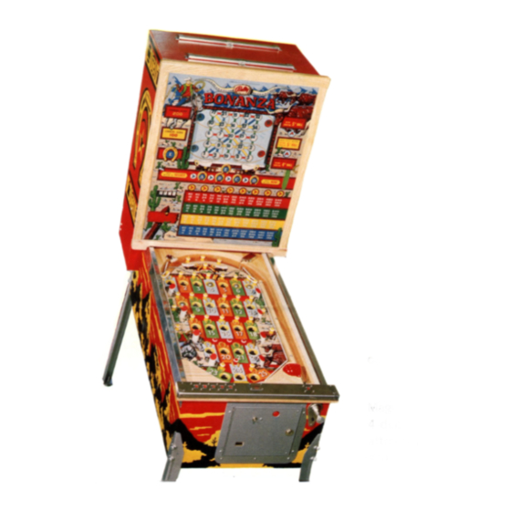
- Page 1 GAME 1085 WINTER 76 SER�ICE MANUAL & PARTS· GUIDE ®'MANUFACTURING CORPORATION 2640 Belmont Avenue • Chicago, lllin_ o is, 60618, U.S.A.· TELEPHONE (312) 267-6060/TELEX NO. 253076/CABLE ADDRESS: BALFAN...
-
Page 2: Table Of Contents
PANEL SHUTTER MOTOR & LIFT START RELAY 35 - FRONT CABINET SWITCH ASSEMBLIES 37 - DIODE MOUNTING BOARD • • • . ALTERNATOR UNIT (EXPORT GAMES) CORNER REPLAY COUNTER - 41 MOTOR PARTS GUIDE BONANZA PARTS GUIDE SERVICE • . • • . - Page 3 MAINTENANCE & SERVIC E SUGGESTIONS To maintain a Game in good working order the game should be kept as clean as possible. Star ting with the Coin Chute, for a great deal of Dirt, Metallic Coin Dust, and sticky beverages collect here.
-
Page 4: Back Door Assembly
:ACK DOOR ASSEMBLY Index Part No. Description Page AS-1020-64 Program Unit Assm. . 28 29 AS-797-399 Red Replay Counter AS-797-399 Yel. Replay Counter AS-797-399 Grn. Replay Counter AS-797-399 Blue Replay Counter . 22 23 E-300-739 7 Relay Bank E-300-861 4 Relay Bank AS-1022-156 Scrambler Unit AS-1110-56... -
Page 5: Back Cabinet Assembly
BACK CABINET ASSEMBLY BONANZA 1 0 8 5 BACK CABINET Index Part No. D�scription Page AS-827-576 Selection Feature Unit AS-827-643 Magic Square Feature . 7 11 AS-2867 Magic Squares Unit . E-300-737 4 Relay Bank AS-473-54 Replay Register E-122-103 Transformer... -
Page 6: Front Cabinet Assembly
FRONT CABINET ASSEMBLY Index Part No. Description Page Ball Lifter Motor Assy. AS-1139-33 AS-186-11 Ball Lifter Assy. AS-187-17 Ball Shooter Assy. Coin, Key Meter E-130-10 Slug Rejector M-1400-Coin AS-982-1133 Sw. & Brkt. Assy. AS-1305-63 Front Molding Assy. AS-1145-52 Ball _Trough & Sw. Assy. M-281-58 Lock Assembly... - Page 7 PLAVFIELD PANEL P ANEL Index Part No. Description Page CA-1100-9 Arch Bottom ASW-Al-30 Ball Runway Sw. C-153 Red Plastic Cover AS-1433-16 Shutter Assembly Panel Switches AS-982-1138 AS-2659-266 "G" Relay Assembly AS-232-95 Shutter Motor Assy. ALWAYS GIVE MODEL AND PART NO. WHEN ORDERING SERVICE PARTS...
- Page 8 MAGIC SQUARES EXPLODED PARTS f>. ®o...
- Page 9 MAGIC SQUARES EXPLODED PARTS Index No. Part No. Description Req. Part No. Description Reg. Index No. P-258-23 Key tvasher MSPR-6 32-1204 Screw Face Plate P-1761 W-923-454 contact Plate LSPR-00632-1102 Screw . . • . • Wiper Link A-3802 Vertical Number Strip 1 c-842 P-2891-3 "E"...
-
Page 10: Magic Squares Maintenance
MAGIC SQUARES MAINTENANCE HOLD DOWN SCREWS � • ® WIPER DISC REPLACEMENTS wiper contact points to corresponding contact points on plate by sliding plate up or down, then tighten 4 When replacing A, B, C, D wipers, position all screws. Next adjust numbers on "E"... - Page 11 MA GIC SQUARES MAINTENANCE LUBRICATION The mounting posts for the plexiglass number discs should always have a touch of lubricating grease. Clutch washers also require lubrication, and when necessary, "Neatsfoot Oil" should be applied. Dry clutches causes loss of clutch action and binding, this is hard on motor unit.
- Page 12 MAGIC SQUARE UNIT Location on Wire Wire Color Part No. Switch/ Coil Functio n Diagram 21-16 Blue MAG IC S Q . E-119-468 Energized by Motor Re. Sws. Controls 50-16 White Moto r movements of Magic Sauare Unit. J- 8 "A"...
-
Page 13: Positions Chart
C. U. SEARCH DISC VVIPER UNIT & POSITIONS CHART PICTORIAL CARD HOLE REFERENCE ® CD @ CD CD CD W @ ® ® GDGD @® CD ®® ®CD ® f1R\ (15\ R\ W W W W K Winners Read Across WIPER POSITIO�l WIPER 1 WIPER 2... - Page 14 CONTROL DISC ASSEMBLY 23-14 21-8 C r. Wiper Fd. from Search Relay Sws. (Q-21) Cir. Fd. from C0-2 Trip Sw. (N-19) 51-11 C r. Wiper Fd. to Green Score Disc (P-35) Cir. Fd. to Blue Replay Cntr. Step-Up Coil (M-32) 18-9 13-2 C r.
-
Page 15: Program Disc Assembly
PROGRAM DISC ASSEMBLY SEE PAGE 18 FOR PROGRAM ASSEMBLY (0-54) 51-4 (L-46) Cir. to Scrambler Disc Wiper Cir. Pd. to "E" Trip Sw. to 3 Step Relay (0-53) 6 3-4 to c.u. Cams 6 & 7 (N-44) Cir. Cir. to 2 Step Relay (0-53) 25-4 (P-44) - Page 16 85-13 Cir. Fd. to C.U. Cam 12 (X8) Sw. (M-19) w.,u r{eJ:l.Lay Cntr. (v '--'-.i..i...Luw Lu. • c.u. c.u. 71-14 Cir. Fd. to Cam 14 (X4) Sw. (a-18) Wiper Fd. Cir. from Pulse Ci 95-6 10-2 Cir. Fd. from Blue Replay Cntr. (Open at 96 Sw.) (N-32) Cir.
- Page 17 �\I �\I� o®®®® @©@®@ @®®©® ®®@@® @o ;4.41 @ " (; 3 ., � ®@ ®o � �41 @ ··� @ � Cv--.a ·· ® P ® P @ 1 ® �f !12®�®t � CIRCUIT FEEDS FROM COIN ·®5 Cb ! �...
-
Page 18: Control Unit Assembly
CON TROL UNIT ASS EMB LY E -119·462 CONTROL UNIT MOTOR ---------------------------------- E-119-462 50/60 Cy. 23. 4 R.P.M. Domestic E-119-370 50 Cy. only 25 R.P.M. Belgium The correct adjustment & synchroni z ation of the Switches controlled by Cam No. 's l0A & 12 is vitally important to the Replay Counter Circuit. - Page 19 CONT ROL UNIT FUNCTION CHART Location on Wire Wire Color Function Part No. Switch/Coil Diagram 20-16 Blue Energized thru Replay Reset Re. E-119-462 CONTROL UNIT 50-16 White Sws. and Timer Cams Index Sws. Motor Opens Circuit to Multi-Play Re. E-14 25-9 Blue-White '/1'1 Pm '.3w/ .
- Page 20 CONTROL UNIT FUNCTION CHART Sw it ch/ Contr ol Part No. Location on Wire Wire Color Function Diagram ASW-Cl-4 K-25 #11 Cam Orange (Multiplier) during winner, pulses (X1 6) N.O. 61-4 Brown-Red corresponding replay counter. ASW-ClX-21 K-24 #11 y Orange (Multiplier) during winner, pulses N.O.
-
Page 21: Program Assembly
PROGRAM ASSEMBLY WIPER ASSEM. AS-1024-134 PROGRAM MOTOR E-119-462 E-119-370 BELGIUM REFLEX FLASH PROGRAM FACTOR INDEX CAMS INDEX INDEX Switch/Coil Part No. Location on Wire Wire Color Function Diagram PRuuRAM E-119-462 20-16 Blue Operates unit through Replay Reset MOTOR 50-16 White Re. - Page 22 4 RELAY BANK- BALL LIFT CAM #6 #1 REFLEX #2 REFLEX -s;; '"o .!2. ..Q. I.Q. � � [fill] JillillJfilillfj[illfil Switch/C oil Part No. Location on Wire Wire Color Functio n Diagram Orange Energized when Ball closes Ball A-20 BALL LIFT G-32-2500 Black-Red Lifter Sw.
- Page 23 4 RELAY BANK REPLAY START MULTI-PLAY ANTI-CHEAT Function Switch/Coi l Part No. Location on Wire Wire Color Diagram Energized through anti-cheat Re. G-30-1500 A-11 REPLAY RESET Orange and Reolav Register Sw. 75-2 Orane-e-White ASW-Rl-3 Completes Circuit to replay reset N.O. E-11 75-2 Orange-White...
-
Page 24: Search Bank
BANK 5 SEARCH SEARCH 5 SEARCH 4 SEARCH 3 SEARCH 2 SEARCH 1 Wire Color Function Switch/Coil Part No. Location on Wire Diagram Energized through 20-5 on RELAY G-28-76 1-64 10-1 Search Disc. 1-65 20-5 Blue Orange-Green N.O. ASW-Rl-8 P-38 Completes Circuit to Search Disc. - Page 25 7 RELAY BANK YELLOW BLUE GREEN SCORE #2 STEP SCORE SCORE #3 STEP ALL SCORES S COR E oi#::=� 0 0,1- - - -t Switch/Coil Part No. Location on Wire Wire Color Function Diagram RED SCORE G-32-2500 J-50 Orange Energized through Scrambler Unit, 54-5 White-Green Disc &...
- Page 26 7 RELAY BANI< Switch/Coil Part No. Location on Wire Wire Color Function Diagram G-30-1500 J-55 Orange Energized from C. U. Cam #6 Sw. ALL SCORE K-54 85-4 Black-White through Coin Counter Unit Disc. ASW-Rl-7 15-6 Red-White Completes Circuit to Red Score N.O.
-
Page 27: Trip Bank
7 TRIP BANK E-119-464 C0-1 Til t "E"Trip Switch/Coil Part No. Location on Wire Wire Color Function Diagram TILT TRIP D-27-425 A-20 Orange Energized by Inertia, Plumb-Bob, 14-5 Red-Green or Anti-Cheat Tilt Circuits. N.C. ASW-B-2 I-49 51-7 White-Red Opens 17 V Circuit 10-1 N.C. - Page 28 7 TRIP BANK Location on Sw itc h/ Co il Part No. Wire Wire Color Function Diagram CO - 2 TRIP D-27-425 J-41 Orange Energized through Program Disc Control Circuit during · Coining of Yellow-Red Game. N.C. ASW-B-2 K-41 31-5 Opens Circuit to this Relay Coil.
- Page 29 RED , VEL.,BLUE,GRN. SCORE UNIT DISCS SCORE DISC WIRES HIRE NUMBERS TOP OF DISC 74-3 BLUE 41-3 63-3 48-3 43-3 10-4 61-4 75-11 36-1 54-6 80-3 71-6 36-14 90-8 98-8 61-4 GREEN 63-12 90-7 41-9 27-6 40-9 60-9 74-9 57-9 YELLOW 51-2 4£...
- Page 30 RED,VEL.,BLUE,&GREEN SCORE UNITS Location on Wire Part No. Diagram No . Switch/Coil Wire Color Function B-25-925 J-57 Orange Energized through Control Circuit RED SCORE Step-Up Coil 15-6 Red-White during coining of game. RED SCORE G-28-1100 D-33 Orange Energized thru Shutter Cam #6 Sw. Re se t Coil 78-3...
- Page 31 REPLAY COUNTERS RED, VEL.,BLU E,GRN. W•7;1·12 WIRE NO. YEL. BLUE GRN. 57-2 40-3 54-6 60-9 50-6 27-8 71-6 74-9 51-2 23-3 74-3 90-8 40-2 10-3 63-3 27-6 93-1 83-2 48-3 40-9 60-6 21-11 75-11 63-12 78-1 60-2 41- , 3 41-9 81-1 74-2...
-
Page 32: Replay Counters
REPL AY COUN TER S RE D, VE L. ,B LU E, &G RN . LOcation on wire Switch/Coi1 Part No. Diagram Wire Color Function B-25-925 M-27 Energized thru Winner Circuit during RED REPLAY Black-Yellow CENTER S. U. Coil 23-12 3-4-5 in Line. -
Page 33: Coin Counter Disc
COIN COUNTER DISC Location on Wire Wire Color Function Switch/ Coil Part No. Diagram B-25-925 Orange Energized through C. U. Cam #5 Sw. COIN COUNTER 57-4 White-Orange Sw. d uring coining of game. Step-Up Coil Energized tht'u Shutter Cam #6 Sw. COIN COUNTER C-28-1100 C-33... -
Page 34: Timer Disc
TIMER DISC Part No. Location on Wire Switch/Coil Wir� Color Function No . Dia ram B-25-925 Orange Energized thru Timer Disc Count Cir- TIMER A-23 cuit for first 5 steps, then thru 1 Step-Up Coil Yellow-Brown Pulse Cam Sw. for remaining steps. Energize range Reset Coil... -
Page 35: Magic Squares Stepper
MAGIC SQUARES STEPPER Part No. Location on Wire Wire Color Function Switch/Coil Diagram MAGIC SQ. B-25-925 J-45 Energized thru Program Disc Control Orange Step-Up Coil Circuit during coining of game. White-Black 58-2 MAGIC SQ. C-28-1100 B-33 Energized thru Shutter Cam #3 Sw. Orange Reset Coil Black-White... -
Page 36: Selection Feature Disc
SELECTION FEATURE DISC Location on Wire Part No. Diagram Wire Color Switch/ Coil F unc tio n SELECTI ON B-25-925 J-42 Orange Energfaed thru Program Disc 80- 7 Step-Up Coil Black Control Circuit. SELECTION C-28-1100 B-33 Orange Ene rgi z ed thr u Shu tter Cam #3 Sw. Reset Coil. -
Page 37: Scrambler Disc
SCRAMBLER DISC Switch/Coil Part No. Wire Color Function Location on Wire No . Diagram Orange Energized thru Shutter Cam #6 Sw. SCRAMBLER B-25-925 A-34 78-3 Orange-Black Step-Up Coil range SCRAMBLER Yellow-Red Reset Coil 31-6 Closed @ "O" 85-5 00000000000000 ,.,.. - ----- •-=-.:-r----- .. - Page 38 PANEL SHUTTER MOTOR UNIT PANEL LIFTER START RELAY E-119-379 LIFTER START RELAY Switch/Coil Part No. Location on Wire Wire Color Function Diagram SHUTTER E-119-379 A-17 Orange . Energized thru start re. circuit or Motor 53-5 White-Yellow anti-cheat circuit. CAM #1 ASW-Cl-27 53-5 F-17...
- Page 39 SHUTTER MOTOR & SVVITCHES Wire Color Function Switch/Coil Part No. Location on Wire Diag-r am N o. When Shutter is closed, completes CAM #5 Whi te-Yellow ASW-C3-8 53-5 B-16 start re. circuit to shutter motor, 10-10 Green-Black· 48-13 when shutter is open, completes start re.
- Page 40 FRONT CABINE T SVV IT CH AS SE M BL IES &C OI L CH A RT S witch /Coil Part No. Location on Wire Wire Color Functio n Diacram ASW-A2-62 83-6 Black-Yellow BALL TROUGH Completes Circuit to B-4 Trip 75-16 Orange-White N.C.
-
Page 41: Diode Mounting Board
SVVITCH ASSEMBLIES &COIL CHART Switch/Coil Part No. Function Wire Color Location on Wire Diae:ram Steps Reflex everytime game is coined REFLEX Orange EA-32-1550 Black Plav Mag. 80-9 Orange Steps Reflex Unit everytime C. U. REFLEX EA-30-1150 J-16 Green-Red Cam #13 Sw. pulses replay register. Replay Mag. -
Page 42: Alternator Unit (Export Games)
ALTERNATOR UNIT NOTE: ALTERNATOR UNIT USED ON EXPORT GAMES. ALTERNATOR PARTS UST Description Part No. 1 Switch ASW-Ml00-1 CT-28-1100 2 Coil . . . • 3 Base Plate A-2214-30 4 Extension Spring SP-100-80 5 Extension Spring SP-100-276 6 Hair Pin M-254 7 Holding Pawl C-708... - Page 43 CORNER REPLA V COUNTER ADJUSTMENTS Must rest into each Tooth on each step without Stop binding. Plate All moving parts must be greased. Tapered Shim See Note #1 Pre-Adjustment moving parts must be greased Stop Plate is Fastened down by screws after Stop Plate is held in fartherest upward position with inser...
-
Page 44: Corner Replay Counter
CORNER REPLAY COUNTER Note #2: Magnet Assembly Adjustment Note #3: Step Adjustment (1) Loosen all the Screws at and (P). (1) Loosen both Screws (M) (L) (Q} (M) (2) Pull back the Switch (J) and Switch Bracket (0) (2) Loosen Lock Nut (A) affthe way away from the Ratchet Assy., and (3) Adjust the Height of the Magnet Assy. - Page 45 MOTOR PARTS GUIDE CONTROL UNIT MOTOR E-119-462 Description Index Part Req. GC3-4023-l Transmission Unit ASS-4023-1 Stator Unit • • ABB-1010-00 Bearing & Brkt. Assy. s-1011-01 Fan • • • • • • • • • Note: Order Index No.'s 5 - 7 as a unit Rotor &...
-
Page 46: Bonanza Parts Guide
BONANZA PARTS GUIDE FRONT C A BINET A S SY . FRONT MOLDING A S SY . Part No. Description Part No. Description CA-1119-51 Front Cabinet AS-1305-63 Front Molding Assy. ( M-281-58 Lock (Replay Switch) (Complete) AS-982-673 P-2210-Coin Coin Drop· Plate... -
Page 47: Service
E-661-4 TYPE 1189-90 LONG EAR TYPE 1380-81 SHORT EAR HAND CRIMPING TOOL HT-1031 REPLACEMENT ITEMS CAN BE ORDERED NOTE: THR U BALLY DIST. OR NEAREST MOLEX REP. IN COUNTRY OF USE. � � T R ACTOR ____ r_,j ffl __ (·...
Need help?
Do you have a question about the BONANZA and is the answer not in the manual?
Questions and answers