
Summary of Contents for RGC PRO400
- Page 1 PRO400 PLATFORM HOIST INSTRUCTIONS REIMANN & GEORGER CORPORATION HOISTING PRODUCTS BUFFALO, NY P/N 6102078 8/29/03...
- Page 2 Insure that the screw securing wire rope end loop to the brake sheave is tight and in good condition. Insure wire rope is reeved properly for two (2) parts of line on the PRO400 hoist. Insure that track support has been properly installed for track lengths over 28 feet.
-
Page 3: Table Of Contents
Assembling the Track Sections .....................6 Mounting the Top Bracket......................6 Raising the Track...........................6 3.6.1 Procedure A...........................7 3.6.2 Procedure B ...........................8 Installing Track Support ........................8 Optional Equipment for the PRO400 Platform Hoist..............9 3.8.1 Plywood Carrier Attachment ......................9 3.8.2 Gravel Hopper Attachment......................10 3.8.3 Roller Angle Guide........................11 OPERATION..........................12 Before Operating the Platform Hoist...................12... - Page 4 LIST OF FIGURES FIGURE DESCRIPTION PAGE PRO400 Platform Hoist Product Nameplate .................3 Platform Wheel Placement Guide ....................5 Platform Assembly ........................5 Bottom Track Section........................6 Track Support Assembly .......................9 Plywood Carrier Assembly......................10 Gravel Hopper Assembly ......................11 Roller Angle Guide Assembly.....................11 Wire Rope Components ......................17 Platform Hoist Assembly Drawing....................20...
-
Page 5: Safety
1 SAFETY 1.1 INTRODUCTION Your Reimann & Georger Corporation PRO400 Platform Hoist has been engineered to provide lifting performance, long term economics and safety advantages that no other type can match. However, even a well-designed and well-built hoist can malfunction or become hazardous in the hands of an inexperienced and/or untrained user. Therefore, read this manual and related equipment manuals thoroughly before operating your hoist to provide maximum safety for all operating personnel, and to get the maximum benefit from your equipment. - Page 6 14. Never stand in-line with the raising or lowering of the platform at either the top or bottom of the hoist track. 15. Never hoist over an open doorway. 16. Never exceed the Rated Load Capacity of 400 pounds for the PRO400 hoist. The Rated Load Capacity is the maximum load that should ever be applied to the hoist.
-
Page 7: Specifications
The platform hoist label should appear as the sample nameplate shown in Figure 2-1. Record the model and serial numbers, and capacity rating for future reference. HOIST CAP. lbs. MODEL SERIAL NO. Figure 2-1. PRO400 Platform Hoist Product Nameplate MODEL__________________________________ SERIAL NUMBER_________________________ CAPACITY RATING_______________________... -
Page 8: Installation And Setup
3.2 COMPLETING THE PLATFORM ASSEMBLY 1. Your PRO400 Platform Lift has an optional unload feature that can be easily added by the installation of the sixteen 2” diameter wheels (#19) using the mounting hardware included in P/N 0401450 Platform Wheel Bag Of Bolts. -
Page 9: Platform Wheel Placement Guide
Figure 3-1. Platform Wheel Placement Guide 6. Refer to Figure 3-2. Fasten the two support braces #16 onto the platform #17 at point “A” & onto the main frame #9 at point “B” with the 1/2 X 1” bolts and nuts. Platform stops #18 can be bolted to the end of the Platform #17 if required. -
Page 10: Mounting The Platform On The Track
A) The upper and middle wheels should contact the rails without application of light pressure. With light pressure on the PRO400 models, the middle and lower wheels should contact the rails. B) Make sure the wooden bumper is not split. Do NOT remove the bumper. -
Page 11: Procedure A
Two methods are suggested for raising the track to its operating position. Refer to either Section 3.6.1 or 3.6.2. 3.6.1 Procedure A 1. Insure a tie rope is holding the platform in position at the base of the track. Lay the assembled track with platform and top bracket attached parallel to the building wall that is to support the track. -
Page 12: Procedure B
WARNING: MAKE SURE THAT BOTH TRACK SHOES ARE RESTING ON A FIRM, LEVEL SURFACE. THIS PREVENTS TRACK SLIPPAGE OR UNEVEN LOADING OF TRACK WHICH CAN CAUSE EQUIPMENT DAMAGE OR PERSONAL INJURY. 3.6.2 Procedure B 1. Insure a tie rope is holding the platform in position at the base of the track. Place track perpendicular to the building with the bottom of the shoes resting against the building to prevent slipping. -
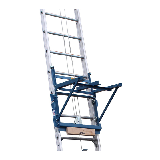
Page 13: Optional Equipment For The Pro400 Platform Hoist
Track Support Track Rail Figure 3-4. Track Support Assembly 3.8 OPTIONAL EQUIPMENT FOR THE PRO400 The following options can customize your hoist for your particular operation. 1. PRO400 Plywood Carrier Attachment 2. PRO400 Gravel Hopper 3. PRO400 Roller Angle Guide 3.8.1... -
Page 14: Gravel Hopper Attachment
Figure 3-5. Plywood Carrier Assembly 3.8.2 Gravel Hopper Attachment 1. Place the #16 braces in the inner holes of the #17 platform. These holes are shown in Figure 3-10. 2. The hinged brackets on the base of the hopper opposite the front legs are mounted to the platform using the loose bolts provided. -
Page 15: Roller Angle Guide
Figure 3-6. Gravel Hopper Assembly 3.8.3 Roller Angle Guide Refer to Figure 3-7. The roller angle guide fits onto hooks provided on the #1 top bracket. It is equipped with conveyor wheels to carry and store material away from the platform discharge on shallow inclines. Figure 3-7. -
Page 16: Operation
9. Check all hooks and sheaves. Replace as necessary. 4.2 RAISING AND LOWERING THE LOAD WARNING: NEVER EXCEED THE RATED LOAD CAPACITY OF 400 POUNDS FOR THE PRO400 HOIST. THE RATED LOAD CAPACITY IS THE MAXIMUM LOAD THAT SHOULD EVER BE APPLIED TO THE HOIST. -
Page 17: Preparing Platform Hoist For Shutdown
1. To raise the load, lift the operator handle slowly with a smooth upward motion. This automatically tightens the drive belt and releases the brake, permitting the platform to roll up the track. 2. When the platform reaches the top of the track, release the operator lever. This action stops the platform and automatically applies the brake, which holds the load and platform. -
Page 18: Disassembly
5 DISASSEMBLY 5.1 PRIOR TO DISASSEMBLY 1. Before disassembling the hoist, read and follow all the safety rules of this manual. Failure to do this can lead to equipment damage and/or serious personal injury. 2. Insure that the platform is not supporting any load before proceeding. 3. -
Page 19: Disassembling The Track Sections
In either case, the track must be turned to make the platform point upwards when the lowering operation is completed. 4. When the track has reached the ground, remove the tie rope holding the platform in position on the track. 5.4 DISASSEMBLING THE TRACK SECTIONS 1. -
Page 20: Inspection And Maintenance
6 INSPECTION AND MAINTENANCE 6.1 GENERAL MAINTENANCE RULES 1. Proper maintenance of the hoist and related equipment consists of adhering to all the guidelines given in this chapter and in the Pre-Hoisting Checklist in the front of this manual. Proper maintenance is required to maintain the system in good condition, which is defined as each part being free of rust or other corrosion, bends, breaks, or other defects. -
Page 21: Safety Hooks
6.4 SAFETY HOOKS The hoist wire rope attaches to the safety hook mounted on the top bracket. If the hook should become broken, bent, or disassembled, it should be replaced immediately. 6.5 WIRE ROPE INSPECTION PROCEDURE Inspect the wire rope prior to each use and at least daily for signs of wear, damage, or pinching. Inspect the entire wire rope working length. -
Page 22: Troubleshooting
7 TROUBLESHOOTING The following chart is intended to assist with troubleshooting the platform hoist. While not all inclusive, the chart outlines the most common causes of a problem and the recommended course of action. SYMPTOM CAUSE AND CORRECTIVE ACTION No oil in engine to build compression—must add oil. Refer to PRO Drive manual for further information. -
Page 23: Parts Lists
8 PARTS LISTS Each item number on the following parts lists can be matched with the item number shown on the corresponding assembly drawing as indicated below. Refer to Figure 8-1. Item Number Part Number Quantity Description 0400574 TOP SHEAVE BRACKET 0400575 SPRING,BOLT, &... - Page 24 Figure 8-1. Assembly Drawing...
- Page 25 LIMITED PRODUCT WARRANTY Reimann & Georger Corporation Hoisting and Construction Products A. LIMITED WARRANTY Reimann & Georger Corporation (the “Manufacturer”) warrants to the original purchaser (the “Buyer”) that all Reimann & Georger Hoisting and Construction products shall be free of defects in material and workmanship for a period of one (1) year from date of original purchase.
- Page 26 H. PROCEDURE FOR WARRANTY PERFORMANCE If the product fails to perform to the Manufacturer’s specifications, the Buyer must provide the Manufacturer with the applicable model and serial numbers, the date of purchase, and the nature of the problem. ADDITIONAL EXCLUSIONS FROM THIS LIMITED WARRANTY. THIS LIMITED WARRANTY DOES NOT COVER ANY OF THE FOLLOWING: 1.
Need help?
Do you have a question about the PRO400 and is the answer not in the manual?
Questions and answers