Table of Contents
Advertisement
Quick Links
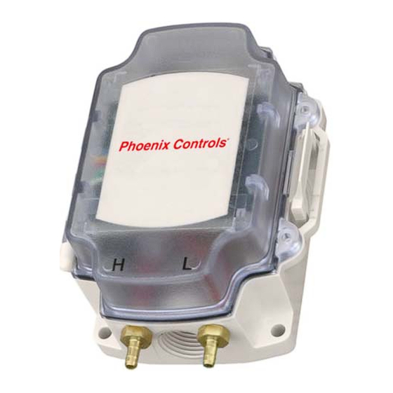
The Fan Static Reset Kit accurately measures the static pressure drop
across a clean air valve and provides feedback to the Building
Management System (BMS) to optimize fan control. The sensor is
housed in a rugged polycarbonate enclosure, which mounts directly to
the valve base channel and has a 3-wire connection to the valve
mounted controller for power and signal. Two pressure pickups, two
pressure dampers and two, six foot lengths of silicon tubing are
included for mounting upstream and downstream of the valve to
obtain optimized pressure readings. One device with a range of 0.0 to
5.0" W.C. covers both medium and low pressure valves and allows for
dynamic fan control to reduce energy consumption under varying
flow conditions.
FEATURES
• Precision sensor provides accurate control feedback value
• Sensor mounts directly on valve base channel
• Pressure value is available network wide
• BMS can dynamically monitor and control fan static
• Maximize energy savings by running fans at lowest possible static
SPECIFICATIONS
Pressure Transmitter
Pressure Range
Output Voltage
Zero Pressure Output
Accuracy
Proof Pressure
Burst Pressure
Corrosion Resistance
Supply Voltage
Power Consumption
Storage Temperature
Operating
Temperature
75 Discovery Way
•
©2010 Phoenix Controls Corporation. Specifications subject to change without notice. Rev. 5/10
0 to 5" W.C. (0 to 1.245 Pa)
0.25 to 4.0 Vdc
0.25 ±0.06 Vdc
1.5% of span (0.0 to 3.0" W.C. at 75° F)
(0 to 747 Pa at 23.9° C)
2.0% of span (3.0 to 5.0" W.C at 75° F.)
(747 to 1245 Pa at 23.9° C)
1 PSI either Port (6.9K Pa)
(performance will be affected)
1.5 PSI either Port (10.4K Pa)
(permanent damage will occur)
Pressure sensor is suitable for clean,
non-corrosive, non-condensing air only
7 to 32 Vac or 7 to 40 Vdc
0.12 VA maximum
40 °F to 203° F (-40° C to 95° C)
32° F to 140° F (0° C to 60° C)
Acton, Massachusetts 01720
F
SPECIFICATIONS (continued)
Temperature
Error
Enclosure
Humidity
Material
Material Rating
Enclosure Rating
Dimensions
Tubing
ID/OD
Wall Hardness
Temperature
Range
Tensile Strength
TABLE OF CONTENTS
Ordering Guide ............................................... 2
Applications ..................................................... 2
Installation ....................................................... 3
Wiring the Pressure Sensor............................... 7
Maintenance .................................................... 9
Troubleshooting ............................................. 10
Phoenix Recommended Wiring ..................... 11
•
Telephone (978) 795-1285
MKT-0266
MPC-1480
S
R
AN
TATIC
ESET
Fan Static Reset Kit
±2% of Span (Over the
Operating Temperature Range)
95% non-condensing
Polycarbonate
UL94, V-0
IP66
4.15" x 5.00" x 2.50"
(105.4 mm x 127 mm x 63.6 mm)
1/8" / 1/4" (3.2 mm / 6.4 mm)
Shore A 70
-137° F to 738° F
(-94° C to 392° C)
1350 PSI
•
Fax (978) 795-1111
F
S
AN
TATIC RESET
K
IT
K
-1
12
IT
OF
Advertisement
Table of Contents

Summary of Contents for Phoenix Controls FSR100
-
Page 1: Table Of Contents
Troubleshooting ..........10 Temperature Phoenix Recommended Wiring ..... 11 75 Discovery Way • Acton, Massachusetts 01720 • Telephone (978) 795-1285 • Fax (978) 795-1111 —1 ©2010 Phoenix Controls Corporation. Specifications subject to change without notice. Rev. 5/10 MKT-0266 MPC-1480 TATIC RESET... -
Page 2: Ordering Guide
FSRs and perform a low-select as system conditions vary. The FSR100 is intended for installation on "Clean air" (Supply or General Exhaust) valves. The materials of construction of the pressure pickup, tubing and the pressure sensor itself are not suitable for applications with corrosive or condensing vapors. -
Page 3: Installation
The further away the pressure pickups are located from the valve and any other obstruction, the more stable and accurate the readings will be. —3 ©2010 Phoenix Controls Specifications subject to change without notice. Rev. 5/10 MKT-0266... - Page 4 It is important that the top and bottom mounting screws are oriented perpendicular to the direction of airflow so as NOTE: not to cause obstructions near the pickup. 12—F TATIC RESET MKT-0266 MPC-1480 ©2010 Phoenix Controls Specifications subject to change without notice. Rev. 5/10...
-
Page 5: Tubing
Make certain that the pressure damper is oriented in the proper direction (arrow pointing AWAY from the pickup) as NOTE: it is not bi-directional. Connect one end of the longer piece of silicon tubing to the pressure damper. —5 ©2010 Phoenix Controls Specifications subject to change without notice. Rev. 5/10 MKT-0266 MPC-1480 TATIC... - Page 6 Secure the tubing to the duct using the enclosed tie wraps and adhesive backed holders, or duct tape so that it cannot become tangled with any moving equipment in the area. Phoenix Controls recommends a "drip loop" somewhere along the tubing run to prevent moisture or WARNING: condensation from reaching the ports on the pressure sensor.
-
Page 7: Wiring The Pressure Sensor
• FSR circuit common wire terminates on TB1, Terminals 2, 4 or 6 (-) Celeris high-speed electric: any available UI (1, 2 or 3) WHITE (SIGNAL) BLACK (CIRCUIT COMMON) RED (POWER) —7 ©2010 Phoenix Controls Specifications subject to change without notice. Rev. 5/10 MKT-0266 MPC-1480 TATIC ESET... - Page 8 LON TX: any available UI (see LON TP/SO for 1, 2 or 3; see below for 4 or 5) WHITE (SIGNAL) BLACK (CIRCUIT COMMON) JUMPER WIRE RED (POWER) 12—F TATIC RESET MKT-0266 MPC-1480 ©2010 Phoenix Controls Specifications subject to change without notice. Rev. 5/10...
-
Page 9: Phoenix Controls Wiring Recommendations
At the BACnet TX controller (BACnet TP, SO and EO controllers cannot be used with FSR100) • FSR power wire terminates on Terminal 25 (24VAC) • FSR signal "+" wire terminates on Terminals 6 or 9 (MULTI_AI) • FSR circuit common wire terminates on Terminals 7 or 10 (COM) A jumper wire is not required on this controller. -
Page 10: Troubleshooting
For example, if 0" W.C. is at 0.45 Vdc and 5" W.C. is at 4.75 Vdc, the Configuration Plug-in scaling needs to indicate 0.45 Vdc = 0" W.C. and 4.75 Vdc = 5" W.C. 12—F TATIC RESET MKT-0266 MPC-1480 ©2010 Phoenix Controls Specifications subject to change without notice. Rev. 5/10... -
Page 11: Phoenix Recommended Wiring
PHOENIX RECOMMENDED CABLES A 3-conductor will typically be used with the FSR100. Cable Plenum Wire Primary Alternate Function Color Code Notes Type Rated Gauge Vendor/Part # Vendor/Part # 24 Vac power to Belden 9409 1: Red Must be Round LOSEA or... - Page 12 The use of greater distances and/or different wire gauges shall comply with the electrical specifications of EIA-485 for MS/TP cable requirements. 12—F TATIC RESET MKT-0266 MPC-1480 ©2010 Phoenix Controls Specifications subject to change without notice. Rev. 5/10...
Need help?
Do you have a question about the FSR100 and is the answer not in the manual?
Questions and answers