
Related Manuals for ECD S80


Summarization of Contents
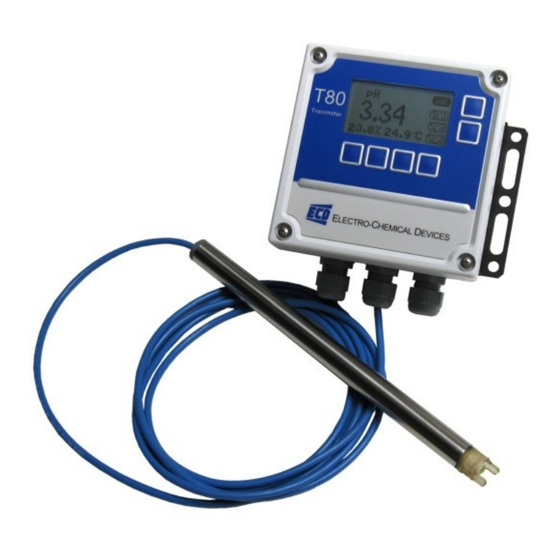
T80 Ease of Use and Display Features
Membrane Switch Navigation
Details navigation using membrane switch controls on the device.
Simple Menu Structure
Highlights the straightforward and intuitive menu design.
Soft Key Menu Choices
Describes the use of soft keys for selecting menu options.
Large LCD Display Readability
Refers to the 2 3/4" x 1 1/2" LCD for easy reading.
T80 Transmitter Inputs, Outputs, and Power
Supported Sensor Inputs
Lists compatible sensor inputs, including S80 and standard pH sensors.
Available Output Signals
Details output options such as 4-20 mA, MODBUS RTU, and HART® 7.
Power Requirement Options
Specifies power options: Loop Powered, 24 VDC, and 110/220 VAC.
S80 Intelligent Sensor 6 Point Advantage
Intelligent Sensor Technology
Highlights the advanced capabilities of the intelligent sensor.
Common Configuration
Emphasizes universal configuration for all measurements.
Application Specific Cartridges
Notes the use of cartridges tailored for specific applications.
Economic Replaceable Cartridges
Points out cost-effectiveness and ease of cartridge replacement.
Submersible and Retractable Designs
Mentions suitability for submersible and retractable installations.
Application Specific Materials
Refers to materials of construction chosen for specific applications.
T80 Home Display Screens Overview
Data Screen Display
Shows Process Variable, % 4-20 mA range, and Temperature.
mV Screen Display
Displays raw mV signal, % 4-20 mA range, and Temperature.
Graphical Screen Display
Offers Line, Bar, or Gauge graphs of Process Variable and range.
T80 Main Menu Navigation Options
CAL Menu Access
Accesses the Calibration functions.
CONFIG Menu Access
Leads to device configuration settings.
INFO Menu Access
Provides access to device information.
SIM Menu Access
Allows simulation of input signals.
HOLD Function
Toggles output hold ON/OFF, freezing 4-20 mA and alarms.
T80 Calibration Procedures
New Sensor Detection
Identifies new sensors and manages calibration registers.
Auto Calibration Method
Details the two-point auto calibration process that recognizes solutions.
Standardize Function
Allows single point adjustment for calibration.
Manual Calibration Entry
Enables manual input of offset and slope values.
Temperature Adjustment
Covers settings for temperature calibration.
T80 Auto Calibration Process Steps
Guided Calibration Workflow
T80 guides the user through the calibration steps.
Standard Value Suggestion and Entry
T80 suggests values; user can accept or enter alternatives.
Continuing Calibration
Option to proceed to the next solution or end calibration.
T80 Auto Calibration Finalization
Second Standard Calibration
Details the process for calibrating with the second standard solution.
Offset and Slope Values Display
Shows the final calibration offset and slope values.
Exiting and Saving Calibration
Steps to exit calibration mode and save changes.
T80 Manual Calibration Steps
Manual Offset and Slope Input
Direct entry of offset and slope values for calibration.
PV and mV Value Entry
Entering process variable and associated mV readings.
Accepting Slope and Saving
Confirming slope entry and saving calibration changes.
T80 Configuration Menu Options
Configure Transmitter Settings
Settings for LCD, Output, Serial, and Password.
Configure Sensor Settings
Options for sensor type, temperature compensation, and isopotential point.
T80 Display Configuration Settings
Display Setup Parameters
Settings for units (°C/°F), contrast, and backlight timeout.
Soft Keys and Graph Types
Configuration of soft keys and graph display modes (Line, Gauge, Bar).
Line Graph Duration Setting
User-configurable duration for line graph display.
Tagging and Pop-Up Features
Configuration for display tagging and pop-up functions.
T80 Output Configuration: 4-20 mA
4-20 mA Range Setup
Defining the minimum and maximum values for the 4-20 mA output signal.
Calibrate 4-20 mA Output
Process for calibrating the 4 mA and 20 mA output points.
4-20 mA Fault Condition Selection
Choosing the current level for fault conditions (e.g., 3.5 mA, 22 mA).
T80 Output Configuration: Relays
Relay Specifications Overview
Details the 3 SPDT relays and their electrical ratings.
Relay Function Selection
Setting relay function to Alarm, Fault, or Disable.
Alarm Set Point Configuration
Configuring set points and delay times for alarm relays.
T80 Hold, Serial, and Password Settings
Output Hold Function Configuration
Setting the 'Time Out' function for output hold.
Serial Communication Settings
Configuration for Address, Baud, and Format for serial communication.
Password Protection Setup
Setting access levels and a 4-character case-sensitive password.
T80 Transmitter Information Display
Transmitter Identification Details
Shows Serial #, revision levels, and software/hardware versions.
Configuration Information
Details on sourcing, communication protocols, and relays.
S80 Sensor Information Display
Sensor Identification and Revision
Displays Process Variable, serial #, and firmware revision.
Sensor Range Information
Shows the configured minimum and maximum sensor range.
Calibration Log Data Access
Access to calibration logs, including offset and slope.
T80 System Simulation Modes
Simulate Process Variable Signal
T80 generates signals equivalent to the process variable.
Fixed Value Simulation
Allows simulation with a manually entered fixed value.
Ramp Simulation Mode
Cycles the PV signal between low and high values with adjustable time.
T80 Relay and 4-20 mA Simulation
Relay Manual Control Simulation
Puts relays under manual ON/OFF control for testing.
4-20 mA Output Simulation
Simulates specific mA output values for testing.
T80 Wiring and Power Board Details
Circuit Board Connection Identification
Explains color coding and connection types on the circuit board cover.
110/220 VAC Power Board Specifications
Details the power board, AC input, 24 VDC out, and preamp options.
T80 Universal Transmitter Key Features Summary
Multi-Measurement Capability
Supports a wide range of measurements with a single transmitter.
Flexible Power Supply Options
Available in Loop Powered, 24 VDC, or 110/220 VAC versions.
Advanced Communication Protocols
Supports HART® 7 or MODBUS RTU communication.
Optional Alarm Relays
Option to include or exclude three alarm relays.
T80 Transmitter Part Numbering Guide
Input Selection Codes
Codes for selecting specific sensor input types.
Power Supply Selection Codes
Codes for choosing the transmitter's power supply type.
Alarm Relays Selection Codes
Codes for including or excluding alarm relays.
Output Protocol Selection Codes
Codes for selecting 4-20mA/MODBUS or HART output.
Mounting Hardware Selection Codes
Codes for various mounting hardware options.
S80 Intelligent Sensor Advantages
Noise-Free Digital Communication
Ensures reliable data transmission without interference.
Plug-and-Play Sensor Calibration
Sensors are calibrated and ready for immediate use.
Easy Maintenance with IP68 Cable
Features a waterproof, detachable cable for simple maintenance.
Component Compatibility with S10/S17
Uses the same cartridges, fittings, and hardware as older sensor models.
Need help?
Do you have a question about the S80 and is the answer not in the manual?
Questions and answers