
Related Manuals for Gintec G10


Summary of Contents for Gintec G10
- Page 1 G10 Multifunctional survey GNSS Receiver User Manual Copyright Guangzhou Geosurv Information Technology Co., Ltd *All Right Reserved...
-
Page 2: Table Of Contents
Brief introduction of G10 ................1 1.2.1 Technical Innovation ................1 1.2.2 Advantage in use ..................2 Chapter 2 G10 Survey System ..................4 2.1 G10 mainframe ....................4 2.1.1 Front side of the mainframe ..............4 2.1.2 Back side of the mainframe ..............5 2.1.3 The bottom of receiver ................ -
Page 3: Chapter 1 Brief Introduction
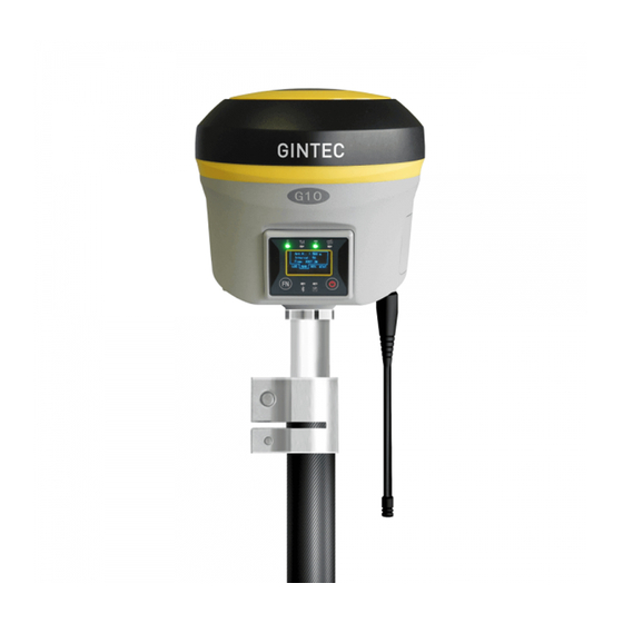
The dimension and weight also has a great breakthrough, now the dimension is diameter 14cm × height 14cm, the weight is just 2kg. Adopt many new technology, there are some new functions add to G10 and this make survey work more convenient. -
Page 4: Advantage In Use
(2) WIFI wireless connection When the WIFI function is opened, G10 can be used as a hotspot. You can connect your phone to it via WIF. Log on the WEB UI, then you can do many configurations with your phone, such as change work mode, change datalink, download static data. - Page 5 (5) Large capacity storage Configure with 4GB internal memory, G10 can store a large amount of survey data. It also support storage expansion, the maximum32GB micro SD card. (6) Productivity tools G10 configures with user-friendly tools, intelligent calibration platform and quick connector.
-
Page 6: Chapter 2 G10 Survey System
Chapter 2 G10 Survey System The first chapter has introduce the company and innovation of G10. But they are all brief. In this chapter, it will show the detailed information of G10, such as appearance, accessories and some basic operation. -
Page 7: Back Side Of The Mainframe
WIFI indicator It will be light when the G10 is connected via WIFI function Satellite indicator How many time it blink, means how many satellites are locked, cycle once every 5seconds Bluetooth indicator It will be light when G10 is connected via... -
Page 8: Basic Operation Of G10
But they are very important 2.2.1 Power on/off This is the first step to use G10, it’s very easy to operate. When the receiver has battery, keep press power key for some seconds, then you will see the LOGO of GINTEC. -
Page 9: Check Work Station
2.2.3 Check work station This section will tell you how to check the work station. Sometimes you want to know the solution, datalink, satellites information and so on. You can press function key to see detailed information Figure 2-4 Work station LOC: Locate coordinate RAW: Antenna height, data internal and frequency RTK: Data difference type, current datalink, work solution state... -
Page 10: Web Ui Function
2.3 WEB UI function G10 has WIFI function, it can work as a hotspot, then Phone, controller, PC and other devices can connect its WIFI. The default WIFI name is device number, there is no password for this WIFI. -
Page 11: Status
Figure 2-8 After connecting the WIFI, input IP “192.168.10.1” into your web browser to open. Then it will pop up a window. It ask for log account and password, default is: Account: admin Password: password The WEB UI contains Status, Information, Download, Management, and Settings. It also can show the device number in the web. -
Page 12: Download
Figure 2-10 Information 2.3.3 Download “Download” is for downloading static data, you can download the datas you want to use, you also can package them together. The format of raw data is “.dat” version, if you want to use “.Rine” version, you can select. Figure 2-11 Download 2.3.4 Managment “Manage”... -
Page 13: Settings
receiver, make self-checking, change the log password and restar the receiver. So “Manage” will be used in many stitons. Figure 2-12 Mnagement 2.3.5 Settings “Settings” includes “Working Mode”, “Device Configuration” and “NMEA message”. All of these functions are very useful. Here will introduce every selection. (1) Working Mode You can select different work mode to configure, static, rover and base. - Page 14 Figure 2-13 Static mode (b) Rover Mode In rover mode, you can select different datalink. Different datalink also has different options can be edited. The datalink includes UHF, Network, External and Bluetooth. If you select UHF mode, then you can select radio channel and radio protocol as you want.
- Page 15 Figure 2-14 Rover Mode (UHF datalink) If you select Network, then besides select satellites system and record raw data, the most important is you can input CORS information, such as IP, account. Then get the mountpoint.
- Page 16 Figure 2-15 Rover Mode (Network datalink) If you select External, then it can connect to external radio. There is a very important thing, the external serial port band rate, this should be same with external radio. Figure 2-16 Rover Mode (External datalink)
- Page 17 Then the last it’s Bluetooth, after selecting the datalink as Bluetooth, there are little option that you can configure. Figure 2-17 Rover Mode (Bluetooth datalink) (c) Base mode Base mode also contains different datalink, most of the parameters are same. The only difference is the base mode has some more options can be edited, shows as follow.
- Page 18 Figure 2-18 Base Mode (2) Device Configuration Device configuration can finish many basic configuration via WEB UI function, such as changing language, select time zone first storage and others. Figure 2-19 Device Configuration (3) NMEA message Here you can configure the NMEA message, turn on/ off them. If you need them out put, you also can select the update frequency.
-
Page 19: Device Register
Figure 2-20 NEMA Message 2.4 Device Register The register code is a 32 digits and letters, there are two ways to register. One is via WEB UI function, another is via controller. The detailed steps as follow 2.4.1 Register via WEB UI As shows in 2.3.4, in when you connect the WIFI of receiver, then select “Manage”, you can see “Registration”. -
Page 20: Register Via Controller
2.4.2 Register via Controller Connect to G10 with our software E-Survey, then it will shows as follow, click “About”. In next window, you can see “Register Instrument”, click it. The last step is inputing the code, then finish registeration. Figure 2-22 Registration via controller 2.5 Upgrade firmware... -
Page 21: Measure The Antenna Height
Figure 2-23 Update Firmware 2.6 Measure the antenna height When we use G10 collect static data or set G10 on a known point as a base station, the antenna height should be measured. Antenna height is actually the vertical height of the phase center to ground measurement point. - Page 22 height = the height from ground to bottom of mainframe + antenna phase center to the bottom of mainframe. (3) Slant height, measure from ground to the up of the mainframe rubber ring. Select slant height in the software, then input the height you measured.
-
Page 23: Chapter 3 Standard Accessories
External radio and controller will be separately introduced. When you order, if you want, you can order the external radio or controller too. 3.1 Base standard accessories 1 G10 receiver UHF & 3G Antennas 2 batteries 1 Adapter... -
Page 24: External Radio Standard Accessories
1 HX SU860T Radio 1 Transmit Antenna 1 Support Pol Power supply Cable 1 Frequency change cable 3.3 Rover standard accessories 1 G10 Receiver UHF & 3G Antenna 2 Batteries 1 Adapter 1 Charger 1 Communication Cable 1 Measure Tape... -
Page 25: Controller Standard Accessories
3.4 Controller Standard Accessories 1 Controller 1 USB cable 1 Adapter 1 Charger 2 Batteries... -
Page 26: Chapter 4 Tilt Survey
Chapter 4 Tilt Survey Tilt survey is the technical function of G10, It is a very practical function. Before make tilt survey, there are some accessories are necessary. It includes 1 G10 receiver, 1 carbon pole, quick connector, mini rotary table and a controller with eSurvey software. -
Page 27: Sensor Calibrate
4.2 Sensor Calibrate Activate tilt survey function is the first step, then it’s “Sensor Calibrate”. Some times when you check “Sensor Calibrate”, it can’t be used. You should check Configure—System Setting, make sure tilt survey function is opened. At the beginning of this chapter, it says that “Sensor Calibrate”... - Page 28 Figure 4-3 Before celebration (left) after celebration (right) (2) Azimuth Calibration Click “Adjust—Sensor Calibrate—Azimuth”, then it will show the “Azimuth calibration” interface. Figure 4-4 As it shows in the interface, there are three steps to do, “Record Vertical, Record Horizontal, Calibrate”. Record vertical and horizontal data is order to get enough data to do the Azimuth Calibrate.
- Page 29 finish a circle, the software will show the picture and have a beep sound. But sometimes, you had finished the circle and the software show the circle, software doesn’t transmit a beep sound and it doesn’t show “Record Horizontal” is successful.
- Page 30 The last step is “Calibrate”. After step one and two, it will show 2 circles on the screen. Then click “Calibrate”, it will calculate the parameter and aske you “Make sure using the parameter?” Click “Yes”, the parameter will be applied. Figure 4-7 (3) Declination Calibration After “Horizontal Calibration”...
- Page 31 Figure 4-9 (b) The second step is “Records Tilt”. In this step, you should collect tilt points in 4 direction, and in every direction you should collect 10 tilt points. There are some conditions to do this step. ① The pole should set on the same points during all of the steps when you are collecting tilt points.
- Page 32 Figure 4-10 Follow these four principles, then you can collect tilt points in four different directions. Each points should has 10 points. As the picture shows, set the pole on one point, when you do this step. The tilt angle is 25°~30°, and make sure the receiver is stable to collect points.
- Page 33 Collect tilt points in four different direction: East South West North Figure 4-12 After success record centers and tilts, then we should apply this parameter to project. Click “Correction” to calculate the parameters, if it exceed the limit, we should do the Sensor Calibrate again.
- Page 34 Click “Correction” to apply. Input the Antenna height, if you use the quick release adapter, the height should be pole height + 0.04m. For example, the pole height is 1.8m, if you use quick release adapter, the height will be 1.84m. Then click “OK” to use. Figure 4-13 Then all steps of Sensor Calibrate are finished.
-
Page 35: Appendix 1 Default Radio Configuration
Appendix 1 Default Radio configuration Channel Frequency Protocol 441.00MHz Trimtalk 450S 442.00MHz Trimtalk 450S 443.00MHz Trimtalk 450S 444.00MHz Trimtalk 450S 445.00MHz Trimtalk 450S 446.00MHz Trimtalk 450S 447.00MHz Trimtalk 450S 448.00MHz Trimtalk 450S The frequency and protocol of Channel 8 can be modified via controller. So you can change it easily. - Page 36 Wireless Communication Radio Modem 2W internal radio receiver and transmitter Radio Frequency 410MHZ-470MHZ Network WCDMA network communication, support HSDPA+, GPRS, GSM Bluetooth Bluetooth 2.1+EDR/ Bluetooth 4.0 dual model Bluetooth WIFI 802.11 b/g/n, support the access point and the client mode Differential Link Support internal network, radio, external input, Bluetooth and WIFI input...
Need help?
Do you have a question about the G10 and is the answer not in the manual?
Questions and answers