
Related Manuals for Honeywell Bendix/King KFC 225


Summary of Contents for Honeywell Bendix/King KFC 225
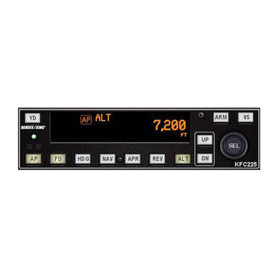
- Page 1 KFC 225 Pilot’s Guide Bendix/King ® Automatic Flight Control System 006-18035-0000 Apr 99...
- Page 2 All rights reserved. Reproduction of this publication or any portion thereof by any means without the express written permission of Honeywell Internatinal Inc. is prohibited. For further information contact the Manager, Technical Publications; Honeywell, One Technology Center, 23500 West 105th Street, Olathe, Kansas 66061.
-
Page 3: Table Of Contents
Table of Contents Introduction ........... . .1 General Description . -
Page 4: Introduction
To aid you in meeting these face with your Silver Crown Plus challenges, Honeywell has devel- package of avionics. Consider the oped the KFC 225 Flight Control advantage of having your avionics System. -
Page 5: General Description
Introduction Introduction General Description The KFC 225 Three Axis system provides lateral, vertical and optional yaw Audio Alert A/P Master Switch modes with altitude preselect. Remote Terminal I/F Connector TRIM (AFCS Maint. Plug) FAIL TRIM KA 285 Trim Fail KCM 100 Remote Mode Annunciaor Configuration... -
Page 6: Power Application And Preflight Tests
Introduction System Operation Power Application and Preflight Tests KFC 225 System Operation Controls and Displays Operation KFC 225 KFC 225 Preflight Test KFC 225 KFC 225 KFC 225 Preflight Test Complete Full KFC 225 Three-Axis with Altitude Preselect Display PITCH AXIS, (P) ANNUNCIA- FLIGHT DIRECTOR (FD) - Page 7 System Operation System Operation NAVIGATION (NAV) MODE sor is less than 50% deflected when 10. VERTICAL TRIM (UP/DN) BUT- 12. VERTICAL SPEED (VS) MODE SELECTOR BUTTON - When armed, the system will automatically TONS - The response of these but- SELECTOR BUTTON –...
- Page 8 System Operation System Operation 14. SELECTED ALTITUDE/VERTI- 17. PITCH AND ROLL MODE, will not operate. If one switch fails or 23. OMNI BEARING SELECT CAL SPEED DISPLAY - Normally AUTOPILOT AND YAW DAMPER is moved and held for 3 seconds, the KNOB - Selects the desired course displays the selected altitude.
-
Page 9: Altitude Alerting And Preselect
System Operation System Operation Altitude Alerting and Preselect Voice Messaging The Altitude Preselect function allows capturing of a selected altitude and The following standard voice mes- transferring into altitude hold. Manual input of selected altitude is accom- sages will be annunciated as condi- plished through the rotary knobs on the faceplate of the KFC 225. -
Page 10: System Operating Modes
System Operation System Operation System Operating Modes The ROL mode engages in wings To initiate a climb or descent from level Roll Attitude Hold mode. Altitude Hold (ALT) mode: To change ROL Attitude Hold Mode: 1. VS button - Press. Note ALT KFC 225 KFC 225 changes to VS and current vertical... -
Page 11: Kfc 225 Detailed System Operation
Detailed System Operation Detailed System Operation KFC 225 Detailed System Operation Takeoff And Climb To Assigned Altitude 080° ı ı ı ı ı ı ı ı KFC 225 KFC 225 KFC 225 KFC 225 1. The aircraft is well off the ground and estab- 2. -
Page 12: Gps Capture
Detailed System Operation Detailed System Operation GPS Capture * Description of GPS operation based on Bendix/King GPS receiver. Others may require different operation. ı ı ı ı ı ı ı ı KFC 225 KFC 225 KFC 225 KFC 225 1. Continuing on heading 010°, a GPS waypoint is 2. -
Page 13: Outbound On Front Course For Procedure Turn To Ils Approach
Detailed System Operation Detailed System Operation Outbound On Front Course For Procedure Turn To ILS Approach 270° ı ı ı ı ı ı ı ı KFC 225 KFC 225 KFC 225 KFC 225 1. The aircraft is heading 270° with heading and 2. -
Page 14: Front Course Ils Approach
Detailed System Operation Detailed System Operation Front Course ILS Approach ı ı ı ı ı ı ı ı KFC 225 KFC 225 KFC 225 KFC 225 1. Continuing the Front Course for Procedure Turn 2. The autopilot is following the localizer. At the 4. -
Page 15: Outbound On Gps Approach
Detailed System Operation Detailed System Operation Outbound on GPS Approach * Description of GPS operation based on Bendix/King GPS receiver. Others may require different operation. ı ı ı ı ı ı ı ı KFC 225 KFC 225 KFC 225 KFC 225 1. -
Page 16: Inbound On Gps Approach
Detailed System Operation Detailed System Operation Inbound on GPS Approach * Description of GPS operation based on Bendix/King GPS receiver. Others may require different operation. ı ı ı ı ı ı ı ı KFC 225 KFC 225 KFC 225 KFC 225 1. -
Page 17: Kcs 55A Compass System
Detailed System Operation KCS 55A Compass System This page intentionally left blank The panel-mounted KI 525A KCS 55A Compass HSI combines the display functions System of both the standard Directional Gyro and the Course Deviation Indicator’s Compass VOR/LOC/Glideslope information to System, which includes the KA 51B provide the pilot with a single pre- Slaving Control and Compensator... -
Page 18: Ki 525A Indicator
KCS 55A Compass System KCS 55A Compass System KI 525A Indicator Selected Course Pointer - On this Heading Select Bug - A movable heading and VOR/LOC/Glideslope two-part arrow, the “head” indicates orange marker on the outer perime- information into one compact dis- 525A Pictorial the desired VOR or Localizer course... -
Page 19: Slaving Meter (Ka 51B)
KCS 55A Compass System KCS 55A Compass System Compass Warning Flag - A red flag KMT 112 Magnetic Slaving labeled “HDG” becomes visible in Transmitter the upper right quadrant of the dis- play whenever the electrical power is This unit senses the direction of inadequate or the directional gyro is the earth’s magnetic field and contin- not up to speed. -
Page 20: Abnormal Circumstances
KCS 55A Compass System KCS 55A Compass System Under some conditions it is possi- 8. The VOR deviation bar represents 12. The glideslope pointers indicate function normally even if a usable ble for the system to stop slaving the selected course, and the rela- the relative position of the glides- glideslope signal is not being exactly 180 degrees from the cor-... -
Page 21: Flight Procedures With The Kcs 55A
KCS 55A Compass System KCS 55A Compass System Flight Procedures with the KCS 55A next ı ı ı ı ı 1. Vectors to Intercept a 3. Turn to Intercept a Victor pages depict a normal Radial Airway The VOR deviation bar begins When the deviation bar is About midway between flight departure from... - Page 22 KCS 55A Compass System KCS 55A Compass System ı ı ı ı ı 8. Airway Interception As you fly over the Columbia Near the Herman intersection Your clearance is V-12 to As you cross the Foristell You are now established on station, the TO/FROM indica- you switch to Foristell VOR- Foristell, then V-14 to the St.
- Page 23 KCS 55A Compass System KCS 55A Compass System HOLDING ILS APPROACH- PATTERN FRONT COURSE ı ı ı ı 1. Approaching the STL VORTAC, the con- 1. You are vectored from the holding pattern 2. Halfway through the outbound turn, the KI 2.
-
Page 24: General Emergency Procedures
KCS 55A Compass System General Emergency Procedures General Emergency Procedures BACK COURSE APPROACH - (REV) Autopilot Malfunction If a back course approach is required, it can be accomplished An autopilot, autopilot trim or manual electric trim malfunction may be recog- as easily as a front course nized as an uncommanded deviation in the airplane flight path or when there approach. - Page 25 General Emergency Procedures This page intentionally left blank Rev. 0 KFC 225 AUTOMATIC FLIGHT CONTROL SYSTEM Apr/99...
- Page 26 Honeywell International Inc. One Technology Center 23500 West 105th Street Olathe, Kansas 66061 FAX 913-791-1302 Telephone: (913) 782-0400 006-18035-0000 Rev. 0 4/99...
Need help?
Do you have a question about the Bendix/King KFC 225 and is the answer not in the manual?
Questions and answers