Siemens OpenAir GIB Series Technical Instructions
Electronic damper actuators, non-spring return 24 vac, floating control, rotary
Hide thumbs
Also See for OpenAir GIB Series:
- Technical basics (44 pages) ,
- Technical instructions (19 pages) ,
- Manual (14 pages)
Advertisement
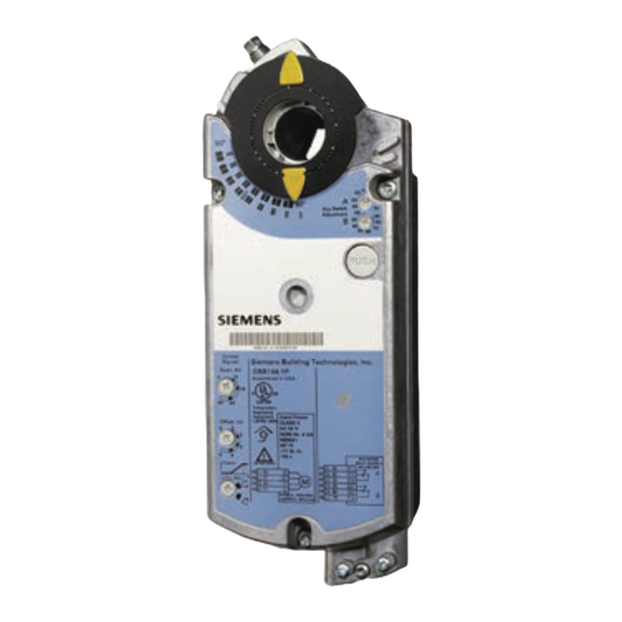
OpenAir™ GBB/GIB Series
Electronic Damper Actuators
Non-spring Return 24 Vac, Floating Control, Rotary
Description
Features
Application
Product Numbers
Torque
221 lb-in (25 Nm)
310 lb-in (35 Nm)
The OpenAir direct coupled 24 Vac, non-spring return (NSR) rotary electric actuator
is designed for floating control of building HVAC dampers.
•
Unique self-centering shaft coupling
•
All metal housing
•
Manual override
•
Independently adjustable dual auxiliary switches available
•
Built in potentiometer option
•
Two torque ranges available
•
UL, CE and cUL listed
These actuators are used in constant or variable air volume installations for the
control of return air, mixed air, exhaust, and face and bypass dampers requiring up to
221 lb-in (25 Nm) or 310 lb-in (35 Nm) torque.
24 Vac Operating Voltage
Cabling
Standard
Plenum
Standard
Plenum
Technical Instructions
Document Number 155-177P25
Table 1.
Potentiometer
Standard
Only
GBB131.1U
GBB132.1U
GBB131.1P
GBB132.1P
GIB131.1U
GIB132.1U
GIB131.1P
EA GBB/GIB-2
June 22, 2015
Auxiliary
Switches
Only
GBB136.1U
GBB136.1P
GIB136.1U
—
GIB136.1P
Siemens Industry, Inc.
Advertisement
Table of Contents

Related Manuals for Siemens OpenAir GIB Series


Summary of Contents for Siemens OpenAir GIB Series
- Page 1 Table 1. 24 Vac Operating Voltage Auxiliary Potentiometer Torque Cabling Standard Switches Only Only Standard GBB131.1U GBB132.1U GBB136.1U 221 lb-in (25 Nm) Plenum GBB131.1P GBB132.1P GBB136.1P Standard GIB131.1U GIB132.1U GIB136.1U 310 lb-in (35 Nm) Plenum GIB131.1P — GIB136.1P Siemens Industry, Inc.
-
Page 2: Specifications
Factory setting 85° Switching hysteresis 2° WARNING: Apply only line voltage or only Class 2 voltage to the switching outputs of both auxiliary switches A and B. Mixed operation is not permissible. See Wiring for details. Page 2 Siemens Industry, Inc. - Page 3 3 feet (0.9 m) length Life cycle Designed for over 60,000 full strokes and a minimum of 1.5 million repositions at rated torque and temperature Noise level <45 dBA (running) Dimensions See Figure 26. Weight 4.4 lbs (2 kg) Siemens Industry, Inc. Page 3...
- Page 4 Kit contains: • Crank arm to attach to the splined hub of the shaft adapter • Mounting bracket Figure 4. Crank Arm Kit with Mounting • Required mounting fasteners Bracket. Page 4 Siemens Industry, Inc.
- Page 5 For dimensions, see Figure 25. 985-106: Provides protection for GIB, GBB and GCA OpenAir actuators in an outside low temperature. Assembly includes: • Weather Shield (ASK75.1U) • Heater Kit (985-105) Figure 9. Heater/Weather Shield Assembly. Siemens Industry, Inc. Page 5...
-
Page 6: Service Parts
4. Auxiliary switch B 5. Auxiliary switch A 6. Position indicator 7. Self-centering shaft adapter 8. Shaft adapter locking clip 9. Position indicator adapter 10. Mounting bracket Figure 12. Components of the Floating Control Actuator. Page 6 Siemens Industry, Inc. -
Page 7: Operation
To change the settings of A and B, use a flat-blade screwdriver to turn the switch adjustment dials to the desired setting at which a signal is to be given. Factory setting Switch A 5° Switch B 85° Figure 13. Dual Auxiliary Switch Dials. Siemens Industry, Inc. Page 7... -
Page 8: Mounting And Installation
The shaft adapter and mounting parts are shipped in a separate container with the actuator. • The actuator is shipped from the factory with a 5° pre-load to ensure tight close off of the damper. Page 8 Siemens Industry, Inc. - Page 9 If the shaft adapter is not resting against the left raised stop, remove the adapter and insert it against the left stop. e. Place the position indicator to the "0" position on the outside scale. See Figure 19. Siemens Industry, Inc. Page 9...
- Page 10 8. Return the actuator to the damper shaft and tighten the shaft adapter to the damper shaft. Figure 20. Mechanical Range Adjustment. Reversing the position Reverse the position indicator so that the counterclockwise 0 to 90 scale is visible. indicator Figure 21. Position Indicator. Page 10 Siemens Industry, Inc.
- Page 11 Black/red Switch B – Normally Closed Black/blue Switch B – Normally Open Black/pink Feedback Potentiometer 0 to 100% P1 – P2 White/red Feedback Potentiometer Common White/blue Feedback Potentiometer 100 to 0% P3 – P2 White/pink Siemens Industry, Inc. Page 11...
- Page 12 Connect wires S4 and S5 to the DMM. The DMM should indicate an open circuit or no resistance. Apply a control signal (24 Vac) to wires 1 (red) and 7 (orange). The DMM should indicate contact closure as the actuator shaft coupling reaches the setting of switch B. Page 12 Siemens Industry, Inc.
-
Page 13: Troubleshooting
The actuator should resume normal operating mode. Dimensions Figure 24. Dimensions of the ASK75.1U Weather Shield in Inches (Millimeters). Figure 25. Dimensions of the ASK75.7U Weather Shield in Inches (Millimeters). Siemens Industry, Inc. Page 13... - Page 14 Information in this publication is based on current specifications. The company reserves the right to make changes in specifications and models as design improvements are introduced. OpenAir is a trademark of Siemens SCHWEIZ AG. Product or company names mentioned herein may be the trademarks of their respective owners.
Need help?
Do you have a question about the OpenAir GIB Series and is the answer not in the manual?
Questions and answers