Table of Contents
Advertisement
Quick Links
Download this manual
See also:
Hardware Manual
Advertisement
Table of Contents

Related Manuals for SkyWave IDP-782


Summary of Contents for SkyWave IDP-782
- Page 1 IDP-782 Hardware Guide T213, Version .10 © SkyWave Mobile Communications Inc. Nov 2014...
-
Page 2: Legal Notice
This documentation is provided on an as-is basis without any warranty of any kind. You assume the entire risk as to the results or performance of the software. Under no circumstance shall SkyWave be held liable for any direct, indirect, consequential, or incidental damages arising from the use or inability to use the software or documentation. -
Page 3: Table Of Contents
IDP-782 - Hardware Guide TABLE OF CONTENTS Legal Notice ............................ ii Contact Information ........................ii List of Figures ..........................vi List of Tables ..........................vii Preface ............................ix Purpose ............................ix Audience ............................ix Errata Sheet ..........................ix Notation ............................ix Reference ............................. - Page 4 Environmental ........................23 3.10 Sensors ..........................24 3.10.1 Temperature Sensor ..................... 24 3.10.2 Accelerometer ......................24 3.11 IDP-782 GPRS - Cellular Module ..................25 3.12 IDP-782 HSPA - Cellular Module ................... 25 3.13 Mechanical ........................26 3.13.1 Transceiver........................26 3.13.2 Cellular Antenna ......................26 3.13.3 Satellite Antenna ......................
- Page 5 IDP-782 - Hardware Guide Connect to Power ......................47 4.7.1 CAN bus Connection ....................48 Connect the Cables ......................48 4.8.1 Connect the Cables ...................... 48 4.8.1.1 Disconnect the FAKRA Connector ..................50 Register the Terminal ....................... 50 4.10 Application Programming Interface ................. 50 4.11 Cleaning Instructions ......................
-
Page 6: List Of Figures
IDP-782 - Hardware Guide List of Figures Figure 1 IDP-782 .......................... 1 Figure 2 System Architecture ....................... 3 Figure 3 Transceiver........................5 Figure 4 Connector Positioning ....................5 Figure 5 Dual SIM Access Door ....................6 Figure 6 LEDs ..........................6 Figure 7 Cellular Antenna ...................... - Page 7 IDP-782 - Hardware Guide Figure 44 Connect the Satellite Antenna ................... 49 Figure 45 Connect the Cellular Antenna ................... 49 Figure 46 Disconnecting the FAKRA Connector from the Transceiver Unit......50 Figure 47 Disconnecting the FAKRA Connector from the Terminal ........56 Figure 48 Locking Clip and Plastic Housing ................
- Page 8 IDP-782 - Hardware Guide THIS PAGE INTENTIONALLY LEFT BLANK T213, Version .10 viii © SkyWave Proprietary...
-
Page 9: Preface
Notation The IDP-782 terminal is available in two models, IDP-782 GPRS (using GPRS) and IDP- 782 HSPA (using both HSPA and GPRS). With the exception of the different cellular modules, all IDP-782 terminals offer the same features and functionality. Throughout this document model names IDP-782 GPRS and IDP-782 HSPA will be used when describing the cellular characteristics of the two models. -
Page 10: Safety Disclaimer
Safety Precautions The terminal must comply with all safety precautions relating to the operation, usage, service and repair of the terminal. SkyWave assumes no liability for the customer’s failure to comply with any of these precautions. Caution warnings appear throughout this document. -
Page 11: Limited Liability
SkyWave’s directors, officers, employees, agents and assigns and for such purposes SkyWave is or shall be deemed to be acting as agent or trustee on behalf of and for the benefit of such companies and persons. -
Page 12: User Serviceable Parts
IDP-782 - Hardware Guide User Serviceable Parts The IDP-782 contains two SIM card holders and may also have SIM cards installed (not supplied by SkyWave). T213, Version .10 © SkyWave Proprietary... -
Page 13: Product Overview
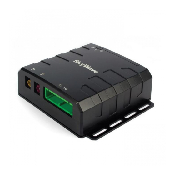
IDP-782 - Hardware Guide Product Overview The IDP-782 (Figure 1) is a high-performance satellite-cellular communication terminal consisting of: A transceiver unit An IsatData Pro satellite modem for communicating with the satellite An integral GPS/GLONASS subsystem I/O interface for wired sensors and devices ... -
Page 14: Overview Of The Messaging System
Global service Service is provided to end users by Solution Providers (SPs) who use the SkyWave IsatData Pro network to offer particular applications and/or services to their clients. The SPs link their application services to the satellite terminals by connecting to the IsatData Pro gateway. -
Page 15: Terminal
AVL market. Feature-rich software tools make application design easy, and shorten the design and testing time. SkyWave also provides consulting services to SPs to help program the terminals and get customer applications running quickly. The terminals include an IsatData Pro satellite modem, a cellular modem with two SIM card slots, and programmable microprocessor and file system for firmware and peripherals. -
Page 16: Terminal Key Features And Benefits
IDP-782 - Hardware Guide Terminal Key Features and Benefits CAUTION Do not rely solely on the terminal for emergency (SOS) calls. The terminal has the following key features and benefits: Designed to be used as a standalone or incorporated into an SP solution ... -
Page 17: Figure 3 Transceiver
IDP-782 - Hardware Guide Figure 3 Transceiver Arranging the transceiver unit’s connectors (Figure 4) at one end of the unit makes installation easier. Sturdy flanges on the side make mounting quick and easy. Figure 4 Connector Positioning 30-Pin Connector Cellular FAKRA Connector (violet) -
Page 18: Cellular Antenna
IDP-782 - Hardware Guide Figure 5 Dual SIM Access Door Mini-B USB Slot SIM Door Optional screw for anti- tamper Figure 6 LEDs Power Status Satellite Cellular Status Status Power and I/O Satellite Antenna Cellular Antenna Connector Connector Connector 1.4.2 Cellular Antenna Terminals use a standard low-profile cellular antenna. -
Page 19: Idp Standard Satellite Antenna
The antenna assembly consists of a single RoHS compliant PCB protected by an IP67 rated waterproof enclosure. The IDP-782 is available with either the standard satellite antenna (Figure 8) or the low elevation satellite antenna (Figure 9). -
Page 20: Pass-Through Mode
IDP-782 - Hardware Guide Figure 9 Low Elevation Satellite Antenna Pass-Through Mode The terminal operates in pass-through mode when there is no valid application firmware present. In pass-through mode, the terminal connects the external RS-232 port to the serial port on its internal modem, making the terminal an IP67 modem that accepts a wide input voltage. -
Page 21: Compliance
IDP-782 - Hardware Guide Compliance Inmarsat Type Approval Pending Industry Canada Pending Pending R&TTE Directive 1999/5/EC (CE Mark) Pending Ingress Protection Cellular antenna: Not waterproof Satellite antenna: IP67 Transceiver unit: IP40 © SkyWave Proprietary... -
Page 22: Specifications
IDP-782 - Hardware Guide Specifications Temperature Parameter Value Operating Temperature -40° to +85°C Storage Temperature -40° to +85°C Reverse Polarity Protection -40 V maximum Electrical 3.2.1 Input Range Parameter Value Power Supply Voltage 9 to 32 V DC T213, Version .10... -
Page 23: Power Consumption
IDP-782 - Hardware Guide 3.2.2 Power Consumption Typical values at ambient temperature with a terminal input voltage of 12 VDC. Table 1 Terminal Input Currents Mode of Operation Condition Satellite Satellite Cellular Current Satellite Rx Burst current for Rx freq. -
Page 24: Accelerometer Power Consumption
IDP-782 - Hardware Guide Table 2 Additional Terminal Input Currents Mode of Operation Port Condition Current Sleep mode Main serial port (cable connected) 0.070 mA AUX serial port (trace enabled and cable connected) 0.033 mA USB main port 37.9 mA... -
Page 25: Sim Holders
IDP-782 - Hardware Guide 3.2.6 SIM Holders The terminal offers the option of a second SIM card. The specifications for both SIM holders are the same. If only using one SIM card, use the main SIM card holder slot. Parameter... -
Page 26: Connector Pin Assignment
IDP-782 - Hardware Guide Figure 10 Transceiver View of Connector 3.4.1 Connector Pin Assignment Table 3 maps to the layout shown in Figure 10. Table 3 Electrical Pin Assignment AUX_RS232 AUX_RS232 Output Output Reserved Reserved CAN_L RS485_B RS485_A Reserved I/O 04... -
Page 27: Input/Output Interface Specifications
IDP-782 - Hardware Guide 3.4.2 Input/Output Interface Specifications The terminal supports four configurable I/O's (I/O 01 to I/O 04): Digital input with weak (1 MΩ) pull-down Digital input with 30-50 K pull-down Digital input with 30-50 K pull-up ... -
Page 28: Digital Output
IDP-782 - Hardware Guide Input Type With weak pull-down Open Open With pull-down Open Closed With pull-up Closed Open The input specifications are provided in the table below. Parameter Min. Typical Max. Units Input low range 1.05 Input high range 1.95... -
Page 29: Analog Input
IDP-782 - Hardware Guide 3.4.2.2.1 Push-pull In the push-pull configuration the output is driven directly from the microprocessor. Parameter Min. Typical Max. Units Output high voltage - open circuit 2.65 3.15 2.85 3.15 Output high voltage (sourcing 25 µA) 2.50 2.80... -
Page 30: Open Drain Outputs
IDP-782 - Hardware Guide Parameter Min Typ Units MΩ Input impedance Minimum measurement voltage Maximum measurement voltage 2.75 3.0 Normal input range Resolution (12 bits) Proportional measurement error INL error Absolute limits 3.4.2.4 Open Drain Outputs The terminal provides two open drain outputs (output05 and output06) that can be used to turn on various devices such as relays, lights or audible alarms. -
Page 31: Pass-Through Mode
IDP-782 - Hardware Guide 3.4.2.5 Pass-Through Mode A terminal can be configured for pass-through mode when there is no application firmware present. A block diagram of pass-through mode is shown in Figure 15. In pass- through mode, the terminal connects the modem's serial interface to the terminal's RS-232 port. - Page 32 IDP-782 - Hardware Guide Interrupting service for receive, transmit. Receive and transmit message queue management. The terminal incorporates a controller area network interface with signaling rates up to 1 Mbps. Note: The user is must provide a termination resistor externally to the terminal.
-
Page 33: Ibutton Reader
IDP-782 - Hardware Guide The electrical characteristics of the interface are: Parameter Minimum Typical Maximum Units Rx Input Low Threshold for DTE -2.7 Connected Rx Input High Threshold for DTE Connected Rx Threshold for DTE Disconnected -0.3 Serial Rx Input Low Threshold... -
Page 34: Rf Specifications
IDP-782 - Hardware Guide The electrical characteristics of the interface are: Parameter Minimum Typical Maximum Units Input High Voltage Input Low Voltage -0.3 Output High Voltage Output Low Voltage ESD Protection Human Body Model ±5 RF Specifications 3.6.1 Standard Antenna... -
Page 35: Memory
IDP-782 - Hardware Guide Parameter GLONASS Accuracy Horizontal Position (CEP) 2.5/2.0 m 4.0 m Velocity 0.1 m/s 0.1 m/s Heading 0.5 degrees 0.5 degrees Memory Parameter Value SRAM 32 Mbit Flash 128 Mbit Environmental Parameter Description Vibration The terminal meets all its specifications during exposure to random vehicular vibration levels per SAE J1455, section 4.9.4.2... -
Page 36: 3.10 Sensors
IDP-782 - Hardware Guide 3.10 Sensors 3.10.1 Temperature Sensor Parameter Value Range -40 to +85°C Accuracy ±2°C (-25 to +85°C) ±3°C (below -25°C) 3.10.2 Accelerometer The terminal has a 3D accelerometer to detect motion in any axis. The accelerometer is important for low power terminals when it is critical to save power when stationary, while quickly detecting when motion has started. -
Page 37: 3.11 Idp-782 Gprs - Cellular Module
IDP-782 - Hardware Guide 3.11 IDP-782 GPRS - Cellular Module Type u-blox SARA-G3 series (SARA-G350) GPRS Module GSM 850/900/1800/1900 MHz Class 4: 33 dBm for EGSM850/900 Output Power Class 1: 30 dBm for GSM 1800/1900 Input Power Peak current of 1.5 A typical. -
Page 38: 3.13 Mechanical
IDP-782 - Hardware Guide peak of current consumption through the VCC pins during a GSM 1-slot Tx burst at maximum Tx power, with a matched antenna GPRS Data Transfer • GPRS multi-slot class 334, coding scheme CS1-CS4, up to 107 kb/s DL, 85.6 kb/s UL •... -
Page 39: Satellite Antenna
IDP-782 - Hardware Guide 3.13.3 Satellite Antenna Figure 16 Satellite Antenna (standard and low elevation) - Bottom View (mm) 2 x 72.4 4 x 5.500 (HOLE) 126.2±0.2 2 x 112.8 35.5±0.2 46.5±0.2 4 x 15.9 3.13.3.1 Standard Antenna Parameter Value... -
Page 40: Low Elevation Antenna
IDP-782 - Hardware Guide 3.13.3.2 Low Elevation Antenna Parameter Value Mass Side entry with 5 m cable: 365 g ® Enclosure Material Xenoy 5220U Color Code WH4E211 (white) ® Sealing Gasket Material Santoprene Figure 17 Low Elevation Antenna Height Dimensions (mm) 76±0.3... -
Page 41: Installation
IDP-782 - Hardware Guide Installation The following section contains recommended installation guidelines for the Solution Provider (SP). These recommendations should be incorporated into installation guidelines for end users. CAUTION The installer is responsible for following all safety guidelines during product installation. Refer to Preface section for details. -
Page 42: Required Tools
4.2.4 Mobile Identification Each terminal has a unique mobile ID used by SkyWave to register it on the IsatData Pro network. This is a 15-digit alphanumeric identifier in the format NNNNNNNNSKYXXXX. The mobile ID is located on the bottom of the terminal and on the shipping box. -
Page 43: Figure 19 Manage Terminals
Keep a copy (APPENDIX B) of the terminal's mobile ID along with the server access ID and password you receive in the activation report email (Figure 20) from SkyWave Customer Support. You need these to communicate remotely with the terminal. -
Page 44: Determine A Suitable Mounting Location
Record the position of the top surface (SkyWave logo) and connector face relative to the ground and the front or side of the vehicle as if you were sitting in the driver's seat. This information is used later to setup the accelerometer service. -
Page 45: Standard Antenna Mounting Guidelines
IDP-782 - Hardware Guide 4.3.1 Standard Antenna Mounting Guidelines CAUTION Mount the antenna at least 20 cm away from humans. CAUTION Cable management and connector strain relief must be incorporated in the installation. Secure the cable no more than 15 cm from the antenna enclosure and at regular intervals along its length as part of the installation to prevent cable wear and eliminate strain on the connector. -
Page 46: Mount The Terminal
IDP-782 - Hardware Guide Mount the Terminal Note: The Solution Provider is responsible for providing mounting instructions if the mounting is to be done using tools or configurations that are different from the ones described in this document. Note: The Installer is responsible for complying with local electrical codes. -
Page 47: Figure 23 Remove An Existing Sim Card
IDP-782 - Hardware Guide Figure 23 Remove an Existing SIM Card Push and release any existing card to remove it 4. Insert the SIM card, circuit down and the notch facing away from you and to the left (Figure 24). -
Page 48: Led Location And Operation
IDP-782 - Hardware Guide 4.4.1.1 LED Location and Operation The terminal has three visible LEDs (Figure 27) to indicate status. Figure 27 LED Location Power Status Cellular Satellite Status Status Terminal Power - Red Indicates that the terminal has external power. This LED is on continuously (solid red) when power is applied. -
Page 49: Led User Control
IDP-782 - Hardware Guide When the LED is under the control of the LSF, the flashing patterns shown in Table 5 are used to indicate the current state of the modem. Table 5 Modem State LED Flashing Patterns Class-Subclass Modem State... -
Page 50: Determine Terminal Orientation For Accelerometer Use
IDP-782 - Hardware Guide a user service to flash the LED four times; the service is responsible for setting a timer allowing it to restart this pattern every 30 seconds [T202]. 4.4.2 Determine Terminal Orientation for Accelerometer Use If using the accelerometer on the terminal, mount the terminal in one of the configurations shown below. -
Page 51: Mount The Antennas
IDP-782 - Hardware Guide Figure 31 Mounting Flange Flange on either side for mounting 2. Drill the mounting holes. 3. Lock the terminal in place with the mounting hardware. CAUTION Torque hardware to a maximum of 2 N-m. Do not over tighten. -
Page 52: Adhesive Mount
IDP-782 - Hardware Guide than 15 cm from the antenna enclosure and at regular intervals along its length as part of the installation to prevent cable wear and eliminate strain on the terminal connector. Damage to the terminal connector interface or cable may result in hardware failure. -
Page 53: Silicone Side Connector Mount
IDP-782 - Hardware Guide Refer to the adhesive manufacturer's recommendations for application temperature, application conditions, compatible bonding materials, and minimum curing times when working with an adhesive. Failure to follow the manufacturer's guidelines could result in the antenna separating from the mounting surface. -
Page 54: Silicone Bottom Connector Mount
IDP-782 - Hardware Guide Figure 34 Apply Silicone to Antenna Do Not Block These Features 5. Place some weight on the antenna while the silicone cures. Figure 35 Weight on the Antenna CAUTION Cable management and connector strain relief must be incorporated in the installation. -
Page 55: Figure 36 Drill Mounting Hole
IDP-782 - Hardware Guide 29 mm minimum drill bit (hole saw) for right angle SMA cable connector Isopropyl alcohol or an equivalent To mount the antenna: 1. Find a location for the antenna following the guidelines provided in Section 4.3.1. -
Page 56: Figure 38 Apply Silicone To Hole In Asset
IDP-782 - Hardware Guide Figure 38 Apply Silicone to Hole in Asset 6. Lower the antenna onto the mounting surface. The straight SMA cable connector can be lowered straight down onto the mounting surface. The right angle SMA cable connector, not shown, must be pivoted down onto the mounting surface to fit the right angle cable and connector through a larger clearance hole. -
Page 57: Cellular Antenna
IDP-782 - Hardware Guide Figure 39 Apply Silicone to Terminal Do Not Block These Features 8. Place some weight on the antenna while the silicone cures. Figure 40 Weight on the Antenna CAUTION Cable management and connector strain relief must be incorporated in the installation. -
Page 58: Route The Main Cable
Note: Remember to leave enough cable slack near the terminal for strain relief so as not to introduce any additional force on the connector. SkyWave recommends securing the cables during installation. Figure 42 Sample Cable Placement in a Vehicle Cab Run the cable assembly following the steps below. -
Page 59: Protect The Cables And Cable Connectors
IDP-782 - Hardware Guide Note: SkyWave recommends that you tape cable ends to prevent dirt from collecting on the contacts. 4.6.1 Protect the Cables and Cable Connectors CAUTION Cable management and connector strain relief must be incorporated in the installation. SkyWave highly recommends... -
Page 60: Can Bus Connection
IDP-782 - Hardware Guide Note: SkyWave recommends that if possible the user wait until the terminal is unblocked (i.e., has a full view of the sky) before powering on the terminal. 1. Locate the main power input and the ground (GND) wires using the connector pin out table (Table 3). -
Page 61: Figure 44 Connect The Satellite Antenna
IDP-782 - Hardware Guide Figure 44 Connect the Satellite Antenna Curry Yellow FAKRA Connector 2. Connect the cellular antenna (Figure 45) to the violet colored FAKRA connector on the terminal by pushing until you hear a click. Figure 45 Connect the Cellular Antenna... -
Page 62: Disconnect The Fakra Connector
Note: The terminals must complete registration to operate. Once you apply power, the terminal goes into satellite search mode to acquire the SkyWave IsatData Pro network. This activity may take a few minutes to complete. If you experience difficulties, refer to Section 5 for troubleshooting suggestions. -
Page 63: 4.11 Cleaning Instructions
IDP-782 - Hardware Guide 4.11 Cleaning Instructions The transceiver and cellular antenna are for indoor use and under normal circumstance should not require any cleaning. However, if cleaning is required, wipe with a damp cloth using a mild detergent if necessary. Do not immerse in water and ensure that water does not enter through the connector openings. -
Page 64: Troubleshooting The Terminal
Check that no objects or debris are on the antenna and blocking transmission. Verify with your SP that the terminal is assigned to your account and registered (i.e., that it is sending and receiving) and that the SkyWave IsatData Pro network is operating properly. ... -
Page 65: Appendix A Order Part Numbers
ST301044-ARC Accessories Terminal development cable ST100320-001 Refer to the SkyWave Catalogue for additional accessories or contact your SkyWave Account Manager. Terminals and antennas come with various options and cable lengths. Contact your Account Executive for additional details. © SkyWave Proprietary... -
Page 66: Appendix B Activation Information
IDP-782 - Hardware Guide Activation Information APPENDIX B Server User Name: ________________________________________________________ Password: _______________________________________________________________ Terminal / Mobile ID IMEI Number/ Location Description (NNNNNNNNSKYXXXX) ICCID number T213, Version .10 © SkyWave Proprietary... -
Page 67: Appendix C Satellite Antenna Dimensions
IDP-782 - Hardware Guide Satellite Antenna Dimensions APPENDIX C CAUTION Before drilling check the template against actual hardware for dimensional accuracy. If it is not correct, DO NOT USE THIS TEMPLATE. Use the physical antenna hardware as a template. CAUTION Cable management and connector strain relief must be incorporated in the installation. -
Page 68: Appendix Dfakra Connector Antenna
IDP-782 - Hardware Guide FAKRA Connector Antenna APPENDIX D Disconnecting the FAKRA Connector 1. Hold the FAKRA connector between your thumb and finger as shown in Figure 47. 2. Press down firmly, with your thumb, on the raised section of the FAKRA thumb release (Figure 47). -
Page 69: Figure 49 Cable Without Housing
IDP-782 - Hardware Guide Figure 49 Cable without Housing Cable / Ferrule Hole 4. Slide the plastic housing back onto the ferrule as far as it can go (Figure 48). Figure 50 Locking Clip (removed) and Plastic Housing Plastic Housing Locking clip (removed) 5. -
Page 70: Figure 53 Insert Inner Conductor
IDP-782 - Hardware Guide Figure 53 Insert Inner Conductor Crimp Ferrule 4. Insert the main body into the braid and dielectric until it pushes against the insulator (Figure 54). Figure 54 Insert Main Body Crimp or Solder 5. Slide the ferrule over the braid and crimp or solder (Figure 55). -
Page 71: Appendix E Mating Cable Assembly Instructions
IDP-782 - Hardware Guide Mating Cable Assembly Instructions APPENDIX E The following section provides the information required to assemble a terminal power/interface cable. Protect the connector pins during assembly and installation. Mating Connector and Terminal Pins Part Numbers The mating connector and crimp contact part numbers are shown in Table 7. - Page 72 Tools Wire Cutter Wire Stripper Crimping Tool Extraction Tool Fine-tip Soldering Iron Solder For production cable assembly, SkyWave recommends the crimping and extraction tools listed in Table 8. T213, Version .10 © SkyWave Proprietary...
-
Page 73: Figure 59 Mating Cable
CAUTION Cable management and connector strain relief must be incorporated in the installation. SkyWave highly recommends securing the cable at regular intervals along its length as part of the installation to prevent cable wear and eliminate strain on the terminal connector. - Page 74 IDP-782 - Hardware Guide THIS PAGE INTENTIONALLY LEFT BLANK T213, Version .10 © SkyWave Proprietary...
-
Page 75: Revision History
IDP-782 - Hardware Guide Revision History Version Date Details Nov 2014 Limited release © SkyWave Proprietary T213, Version .10... -
Page 76: Acronyms/Glossary
IDP-782 - Hardware Guide Acronyms/Glossary Controller Area Networks COFETEL Comisión Federal de Telecomunicaciones (Federal Telecommunications Commission of Mexico) direct current Enhanced GSM EGSM Electrostatic Discharge encapsulating security payload Federal Communications Commission ground General Packet Radio Service GPRS Global Positioning System... -
Page 77: Index
IDP-782 - Hardware Guide Index… activation ..........30, 50 ingress protection ........9 Activation Report ........31 IsatData Pro network antenna description ..........2 assembly standard antenna ...... 7 features............ 2 cable bend radius ........33 maximum messages from-mobile ... 2 cellular antenna description ..... - Page 78 www.SkyWave.com...
Need help?
Do you have a question about the IDP-782 and is the answer not in the manual?
Questions and answers