Sign In
Upload
Download
Add to my manuals
Delete from my manuals
Share
URL of this page:
HTML Link:
Bookmark this page
Add
Manual will be automatically added to "My Manuals"
Print this page
×
Bookmark added
×
Added to my manuals
Manuals
Brands
S&P Manuals
Fan
ERV TRC1600 P1
Installation, operation & maintenance manual
S&P ERV TRC1600 P1 Installation, Operation & Maintenance Manual
Energy recovery ventilator
Hide thumbs
1
2
3
4
5
6
7
8
9
10
11
12
13
14
15
16
17
18
19
20
21
22
23
24
page
of
24
Go
/
24
Bookmarks
Advertisement
Quick Links
Download this manual
INSTALLATION, OPERATION & MAINTENANCE MANUAL
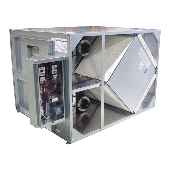
ENERGY RECOVERY VENTILATOR
TRC1600
WWW.SOLERPALAU-USA.COM
Previous
Page
Next
Page
1
2
3
4
5
Advertisement
Need help?
Do you have a question about the ERV TRC1600 P1 and is the answer not in the manual?
Ask a question
Questions and answers
Related Manuals for S&P ERV TRC1600 P1
Fan S&P TR90 Series Installation And Operation Manual
(17 pages)
Fan S&P ERV TRC1600 P3 Installation, Operation & Maintenance Manual
Energy recovery ventilator (24 pages)
Fan S&P TRC1200RT Installation, Operation & Maintenance Manual
Energy recovery ventilator (28 pages)
Fan S&P TRCeN Series Installation, Operation & Maintenance Manual
Energy recovery ventilators (28 pages)
Fan S&P MIXVENT TD Series Installation And Wiring Instructions
Mixed flow in line duct exhaust fans (12 pages)
Fan S&P TD-250/100 Manual
(6 pages)
Fan S&P TD SILENT Series Instruction Manual
(53 pages)
Fan S&P TD-SILENT Series Instruction Manual
(52 pages)
Fan S&P TD-500/150-Silent Instruction Manual
(64 pages)
Fan S&P TD SILENT Series Instruction Manual
Duct silent diagonal fan (92 pages)
Fan S&P TD SILENT Manual
(64 pages)
Fan S&P TD-1300/250 SILENT 3V Instruction Manual
(7 pages)
Fan S&P TD-355 Installation And Wiring Instructions
Mixed flow in line duct exhaust fans (12 pages)
Fan S&P TD - ECOWATT TD-160/100 Instruction Manual
(56 pages)
Fan S&P THGT Series Instruction Manual
Smoke extract fans (36 pages)
Fan S&P TD-4000 Manual
(48 pages)
This manual is also suitable for:
Erv trc1600 p3
Print
Rename the bookmark
Delete bookmark?
Delete from my manuals?
Login
Sign In
OR
Sign in with Facebook
Sign in with Google
Upload manual
Upload from disk
Upload from URL


Need help?
Do you have a question about the ERV TRC1600 P1 and is the answer not in the manual?
Questions and answers