
Related Manuals for SEW-Eurodrive MOVIGEAR classic MGF**1-DSM-C Series


Summary of Contents for SEW-Eurodrive MOVIGEAR classic MGF**1-DSM-C Series
- Page 1 *25805134_0718* Drive Technology \ Drive Automation \ System Integration \ Services Operating Instructions Drive Unit ® MOVIGEAR classic MGF..1-DSM-C Edition 07/2018 25805134/EN...
- Page 2 SEW-EURODRIVE—Driving the world...
-
Page 3: Table Of Contents
Table of contents Table of contents General information........................ 5 About this documentation .................... 5 Other applicable documentation .................. 5 Structure of the safety notes ................... 5 Rights to claim under limited warranty ................ 6 Product names and trademarks.................. 6 Copyright notice ...................... 7 Safety notes .......................... 8 Preliminary information .................... 8 Duties of the user...................... 8 Target group ........................ 8... - Page 4 Table of contents Installation topologies .................... 58 Terminal assignment..................... 60 Thermal motor protection.................... 61 Startup ............................. 63 Startup notes......................... 63 Prerequisites for startup.................... 63 Service ............................. 64 Malfunctions of the mechanical drive................ 64 SEW‑EURODRIVE Service .................. 66 Extended storage...................... 66 Waste disposal...................... 68 Inspection and maintenance .................... 69 Inspection and maintenance intervals................ 69 Lubricant change intervals .................... 71 Inspection and maintenance work ................ 72 Changing the oil ...................... 73...
-
Page 5: General Information
General information About this documentation General information About this documentation The current version of the documentation is the original. This documentation is an integral part of the product. The documentation is written for all employees who assemble, install, start up, and service this product. Make sure this documentation is accessible and legible. -
Page 6: Rights To Claim Under Limited Warranty
General information Rights to claim under limited warranty Meaning of the hazard symbols The hazard symbols in the safety notes have the following meaning: Hazard symbol Meaning General hazard Warning of dangerous electrical voltage Warning of hot surfaces Warning of risk of crushing Warning of suspended load Warning of automatic restart 1.3.3... -
Page 7: Copyright Notice
General information Copyright notice Copyright notice © 2018 SEW‑EURODRIVE. All rights reserved. Unauthorized reproduction, modifica- tion, distribution or any other use of the whole or any part of this documentation is strictly prohibited. ® Operating Instructions – MOVIGEAR classic... -
Page 8: Safety Notes
Safety notes Preliminary information Safety notes Preliminary information The following general safety notes have the purpose to avoid injury and damage to property. They primarily apply to the use of products described in this documentation. If you use additional components also observe the relevant warning and safety notes. Duties of the user As the user, you must ensure that the basic safety notes are observed and complied with. -
Page 9: Designated Use
Safety notes Designated use Specialist for elec- Any electrotechnical work may only be performed by electrically skilled persons with a trotechnical work suitable education. Electrically skilled persons in the context of this documentation are persons familiar with electrical installation, startup, troubleshooting, and maintenance of the product who possess the following qualifications: •... -
Page 10: Installation/Assembly
Safety notes Installation/assembly If necessary, use suitable, sufficiently dimensioned handling equipment. Observe the information on climatic conditions in chapter "Technical data" of the docu- mentation. The following figure shows the position of the lifting eye. 28228871 21488241163 Installation/assembly Ensure that the product is installed and cooled according to the regulations in the doc- umentation. -
Page 11: Electrical Connection
Safety notes Electrical connection 2.6.1 Restrictions of use The following applications are prohibited unless explicitly permitted: • Use in potentially explosive areas • Use in areas exposed to harmful oils, acids, gases, vapors, dust, and radiation • Operation in applications with impermissibly high mechanical vibration and shock loads in excess of the regulations stipulated in EN 61800-5-1 •... -
Page 12: Startup/Operation
Safety notes Startup/operation Startup/operation Observe the safety notes in the chapters "Startup" and "Operation" in the documenta- tion. Make sure that the present transport protection is removed. Do not deactivate monitoring and protection devices of the machine or system even for a test run. -
Page 13: Unit Structure
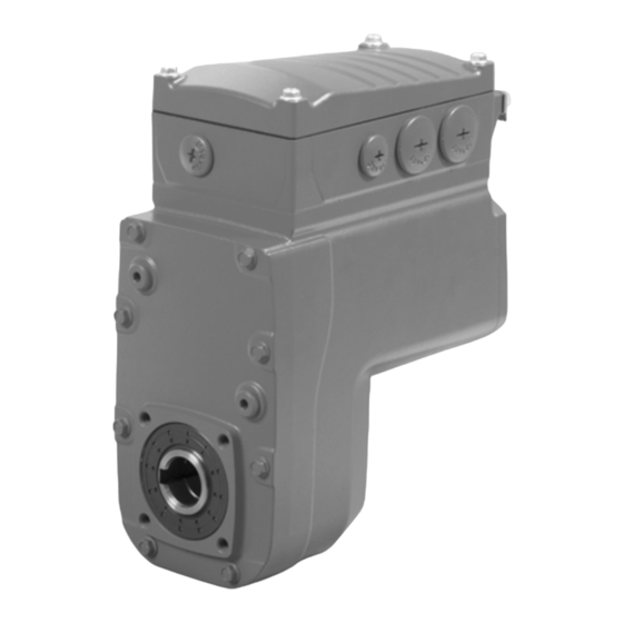
Unit structure MOVIGEAR® classic drive unit Unit structure MOVIGEAR ® classic drive unit ® MOVIGEAR classic drive unit ® MOVIGEAR classic is a unit consisting of a gear unit and a synchronous motor in a compact aluminum die-cast housing (see following figure). MGF..1-DSM-C 21491248523 Cover... -
Page 14: Shaft Types
Unit structure Shaft types Shaft types ® MOVIGEAR classic is available with the following shaft variants: ® 3.2.1 MOVIGEAR classic with hollow shaft and keyway (MGFA.) ® The following figure shows a MOVIGEAR classic unit with hollow shaft and keyway: 21491880203 ®... -
Page 15: Housing Mounting
Unit structure Housing mounting Housing mounting 3.3.1 Torque arm (MGF.T) ® The following figure shows the torque arm for MOVIGEAR classic: 21491911691 3.3.2 Housing with threads (MGF.S) WARNING Improper installation of the drive unit without torque arm. Severe or fatal injuries. •... -
Page 16: Threads For Protective Cover
Unit structure Threads for protective cover Threads for protective cover NOTICE Impermissible use of the threads. Damage to the drive unit. • The threads may only be used for other applications after consultation with SEW‑EURODRIVE. • SEW‑EURODRIVE assumes no guarantee or liability for resulting product dam- ages. -
Page 17: Nameplate Position
Unit structure Nameplate position 3.5.1 Overview The following figure shows the possible cable entries: 21491919115 Nameplate position ® The following nameplate positions are possible for MOVIGEAR classic: • • • 3 (standard position) 3.6.1 Overview The following figure shows the possible positions: 76646 Bruchsal/Germany eff% 81.2 MGFAT1-DSM-C/PE... -
Page 18: Example Nameplate And Type Designation Of Drive Unit
Unit structure Example nameplate and type designation of drive unit Example nameplate and type designation of drive unit 3.7.1 Nameplate ® The following figure gives an example of a MOVIGEAR classic nameplate. For the structure of the type designation, refer to chapter "Type designation". 76646 Bruchsal/Germany eff% 81.2 MGFAT1-DSM-C/PE... -
Page 19: Cover And Connection Box
Unit structure Cover and connection box Cover and connection box ® The following figure shows the connection box and cover on the MOVIGEAR classic MGF..1-DSM-C: [2] [3] [4] [5] PE W 21491922059 Cable glands Connection box Terminals for internal wiring Part number of the connection board Terminals X2 for motor connection PE, W, V, U Cover... -
Page 20: Mechanical Installation
Mechanical installation Installation notes Mechanical installation Installation notes INFORMATION Adhere to the safety notes during installation. WARNING Improper installation/disassembly of drive unit and mount-on components. Serious injuries. • Adhere to the notes about installation and disassembly. • Before releasing shaft connections, make sure that there are no active torsional moments present (tensions within the system). -
Page 21: Required Tools And Resources
Mechanical installation Required tools and resources Required tools and resources • Set of wrenches, set of screwdrivers, set of socket wrenches • Torque wrench • Mounting device • Compensation elements (shims and spacing rings), if necessary • Fasteners for output elements ®... -
Page 22: Setting Up The Drive Unit
Mechanical installation Setting up the drive unit Setting up the drive unit 4.4.1 Notes • Only mount the drive units to the plant structure together with a torque arm. Install- ation without a torque arm is not permitted. • Clean the shaft ends thoroughly to ensure they are free of anti-corrosion agents (use a commercially available solvent). - Page 23 Mechanical installation Setting up the drive unit 4.4.3 Installation in damp areas or in the open Drives are supplied in corrosion-resistant versions for use in damp areas or in the open. Repair any damage to the paint work if necessary. 4.4.4 Derating depending on the installation altitude The following diagram shows the factor f...
- Page 24 Mechanical installation Setting up the drive unit 4.4.6 Gear unit venting Drive units with installed breather valve Except for the mounting position M3, SEW‑EURODRIVE delivers all drive units ordered for a specific mounting position with a breather valve that is activated and in- stalled according to the specific mounting position.
- Page 25 Mechanical installation Setting up the drive unit Activating the breather valve After installing the breather valve, activate it as follows. For designs with the breather valve screwed in: Check whether the breather valve is activated. If not, you have to re- move the transport fixture of the breather valve before you start up the drive unit.
- Page 26 Mechanical installation Setting up the drive unit 4.4.7 Pressure compensation on electronics (option /PE) Designs with included pressure compensation fitting (option /PE) On designs with an included pressure compensation fitting (option /PE), you must in- stall the fitting depending on the mounting position used. The tightening torque is 4.0 Nm.
-
Page 27: Shaft-Mounted Gear Unit With Keyway
Mechanical installation Shaft-mounted gear unit with keyway Shaft-mounted gear unit with keyway INFORMATION Observe the design notes in chapter "Technical data and dimension sheets" for the customer shaft design. 4.5.1 Installation notes ® 1. Apply NOCO fluid and spread it thoroughly. 21513616267 21513618699 2. -
Page 28: (Customer Shaft Without Contact Shoulder)
Mechanical installation Shaft-mounted gear unit with keyway 2A: Standard installation procedure 21513623051 Short retaining screw (standard Retaining ring scope of delivery) Lock washer Customer shaft Washer 2B: Installation with the SEW‑EURODRIVE assembly/disassembly kit Customer shaft with contact shoulder 21513626507 Observe chapter "Technical data and dimension sheets / Design notes for gear units with hollow shaft and key". - Page 29 Mechanical installation Shaft-mounted gear unit with keyway 2C: Installation with the SEW‑EURODRIVE assembly/disassembly kit Customer shaft without contact shoulder 21513628939 Observe chapter "Technical data and dimension sheets / Design notes for gear units with hollow shaft and key". Retaining screw Retaining ring Lock washer Spacer tube...
- Page 30 Mechanical installation Shaft-mounted gear unit with keyway 4.5.2 Disassembly notes WARNING Risk of burns due to hot surfaces. Serious injuries. • Let the devices cool down before touching them. INFORMATION For information on the SEW‑EURODRIVE assembly/disassembly kit, see chapter "Technical data and dimension sheets / Design notes". The following description only applies when the drive is assembled using the SEW‑EURODRIVE assembly/disassembly kit (see previous description, points 2B or 2C).
- Page 31 Mechanical installation Shaft-mounted gear unit with keyway 5. Screw the retaining screw [1] back in. Now you can force the drive off the shaft by tightening the bolt. 21513728267 Retaining screw Fixed nut Retaining ring Forcing washer Customer shaft ® Operating Instructions –...
- Page 32 Mechanical installation Shaft-mounted gear unit with TorqLOC® (customer shaft without contact shoulder) Shaft- mounted gear unit with TorqLOC® (customer shaft without contact shoulder) ® Shaft-mounted gear unit with TorqLOC (customer shaft without contact shoulder) 1. Clean the customer shaft and the inside of the hollow shaft. Ensure that all traces of grease or oil are removed.
- Page 33 Mechanical installation Shaft-mounted gear unit with TorqLOC® (customer shaft without contact shoulder) 5. Push the gear unit onto the customer shaft. 21528908171 6. Preassemble the torque arm on the plant structure / holding fixture (do not tighten the screws). 21528910603 7.
- Page 34 Mechanical installation Shaft-mounted gear unit with TorqLOC® (customer shaft without contact shoulder) 8. Push the stop ring to the bushing. Mark the position of the stop ring. 21528915467 9. Remove the torque arm from the holding fixture / plant structure. 21528917899 10.
- Page 35 Mechanical installation Shaft-mounted gear unit with TorqLOC® (customer shaft without contact shoulder) 12. Tighten the stop ring using the appropriate torque as specified in the table below. 9007220783054347 Type Tightening torque Standard design Stainless steel MGFT.1 18 Nm 7.5 Nm 13. Push the bushing and the gear unit onto the customer shaft up to the fixed stop ring.
- Page 36 Mechanical installation Shaft-mounted gear unit with TorqLOC® (customer shaft without contact shoulder) 15. Make sure that all screws are loosened and slide the shrink disk onto the hollow shaft. 9007220783624843 16. Slide the counter bushing onto the customer shaft and into the hollow shaft. 9007220783627275 17.
- Page 37 Mechanical installation Shaft-mounted gear unit with TorqLOC® (customer shaft without contact shoulder) 19. Make sure that the customer shaft is seated in the counter bushing. 9007220783632139 20. Only tighten the screws of the shrink disk hand-tight and ensure that the outer rings of the shrink disk are parallel.
- Page 38 Mechanical installation Shaft-mounted gear unit with TorqLOC® (customer shaft without contact shoulder) > 0 mm > 0 mm > 0 mm 21528898443 23. Securely tighten the torque arm; observe chapter "Torque arm". 21528903307 ® Operating Instructions – MOVIGEAR classic...
- Page 39 Mechanical installation Shaft-mounted gear unit with TorqLOC® (customer shaft with contact shoulder) Shaft- mounted gear unit with TorqLOC® (customer shaft with contact shoulder) ® Shaft-mounted gear unit with TorqLOC (customer shaft with contact shoulder) 1. Clean the customer shaft and the inside of the hollow shaft. Ensure that all traces of grease or oil are removed.
- Page 40 Mechanical installation Shaft-mounted gear unit with TorqLOC® (customer shaft with contact shoulder) 3. Slide the bushing onto the customer shaft. 0 mm 21528993931 ® 4. Apply NOCO fluid on the bushing and spread thoroughly. 21528996363 5. Push the gear unit onto the customer shaft. 21528998795 ®...
- Page 41 Mechanical installation Shaft-mounted gear unit with TorqLOC® (customer shaft with contact shoulder) 6. Make sure that all screws are loosened and slide the shrink disk onto the hollow shaft. 9007220783742219 7. Slide the counter bushing onto the customer shaft and into the hollow shaft. 9007220783744651 8.
- Page 42 Mechanical installation Shaft-mounted gear unit with TorqLOC® (customer shaft with contact shoulder) 10. Make sure that the customer shaft is seated in the counter bushing. 9007220783749515 11. Only tighten the screws of the shrink disk hand-tight and ensure that the outer rings of the shrink disk are parallel.
- Page 43 Mechanical installation Shaft-mounted gear unit with TorqLOC® (customer shaft with contact shoulder) 14. The remaining gap between counter bushing and hollow shaft end must be > 0 mm. > 0 mm > 0 mm 21528986635 15. Mount the torque arm and tighten it securely; observe chapter "Torque arm". 21528989067 ®...
-
Page 44: Shaft-Mounted Gear Unit With Torqloc - Disassembly, Cleaning, Lubrication
Mechanical installation Shaft-mounted gear unit with TorqLOC® – disassembly, cleaning, lubrication Shaft- mounted gear unit with TorqLOC® – d isassembl y, cleaning, lubrication ® Shaft-mounted gear unit with TorqLOC – disassembly, cleaning, lubrication 4.8.1 Removal notes WARNING Risk of burns due to hot surfaces. Serious injuries. - Page 45 Mechanical installation Shaft-mounted gear unit with TorqLOC® – disassembly, cleaning, lubrication 4.8.2 Cleaning and lubrication There is no need to dismantle removed shrink disks before they are reinstalled. Clean and lubricate the shrink disk if it is dirty. Lubricate the tapered surfaces with one of the following solid lubricants: Lubricant (Mo S2) Sold as Molykote 321 (lube coat)
-
Page 46: Installing The Protective Cover
Mechanical installation Installing the protective cover Installing the protective cover WARNING Risk of injury caused by rapidly moving output elements. Serious injuries. • Disconnect the drive unit from the power supply and safeguard it against uninten- tional power up before you start working on it. •... - Page 47 Mechanical installation Installing the protective cover 3. The following figure shows the installed safety cover: CLOSE OPEN OPEN CLOSE 21514203531 4.9.2 Installation without cover In certain individual cases (e.g. through-shaft), you cannot install the safety cover. In these cases, the safety cover is not necessary if the system or unit manufacturer provides corresponding components to guarantee for the compliance with the required degree of protection.
-
Page 48: Torque Arm
Mechanical installation Torque arm 4.10 Torque arm NOTICE Improper assembly may damage the drive unit. Possible damage to property. • Do not place torque arms under strain during installation. • Always use bolts of quality 8.8 to fasten torque arms. INFORMATION The bolts required can be enclosed with delivery, when required. -
Page 49: Tightening Torques
Mechanical installation Tightening torques 4.11 Tightening torques WARNING Risk of burns due to hot surfaces. Serious injuries. • Let the devices cool down before touching them. 4.11.1 Blanking plugs Tighten the plastic blanking plugs included in the delivery by SEW‑EURODRIVE with 2.5 Nm. - Page 50 Mechanical installation Tightening torques 4.11.2 Cable glands Tightening torques Tighten the EMC cable glands optionally supplied by SEW‑EURODRIVE to the fol- lowing torques: Screw fitting Part Contents Size Outer Tighten- number cable dia- meter torque EMC cable glands 18204783 10 pieces M16 × 1.5 5 to 9 mm 4.0 Nm (nickel-plated brass) 18204805 10 pieces...
- Page 51 Mechanical installation Tightening torques 4.11.3 Cover Proceed as follows when installing the cover: Insert the screws and tighten them in diametrically opposite sequence step by step with a tightening torque of 6.0 Nm. 21524162315 ® Operating Instructions – MOVIGEAR classic...
-
Page 52: Electrical Installation
Electrical installation Equipotential bonding Electrical installation Equipotential bonding Regardless of the PE connection, it is essential that low-impedance, HF-capable equipotential bonding is provided (see also EN 60204-1 or DIN VDE 0100-540): • Establish a connection over a wide surface area between the drive unit and the mounting rail. -
Page 53: Equipotential Bonding At The Connection Box
Electrical installation Equipotential bonding at the connection box Equipotential bonding at the connection box Another option for HF-capable equipotential bonding at a connection box is the follow- ing cable gland with M6 stud bolt: 3884960907 Tightening Tightening Part number torque on cable torque on M6 nut gland for stud bolt... -
Page 54: Installation Instructions
Electrical installation Installation instructions Installation instructions 5.3.1 Thermal motor protection NOTICE Faulty installation. Electromagnetic interference of the drives. • Install the connecting lead of the PK (PT1000) separately from other power cables maintaining a distance of at least 200 mm. Laying together is only permit- ted if either the cable of the PK (PT1000) or the power cable is shielded. - Page 55 Electrical installation Installation instructions 5.3.3 Activating the terminals (only designs with cage clamp terminals) Activating terminals X2 for motor connection Adhere to the following sequence when activating the terminals X2 for motor connec- tion: Terminals X2 for motor connection (the following figure shows a schematic il- lustration) 22904853003 ®...
- Page 56 Electrical installation Installation instructions Activating terminals X4 for temperature sensor Adhere to the following sequence when activating the terminals X4 for temperature sensor: Before removing the conductor, first press the actuation button on top. Terminals X4 for temperature sensor (the following figure shows a schematic illustration) Connect conductor, Connect conductor, without pushing the activation button.
- Page 57 Electrical installation Installation instructions 5.3.4 Notes on PE connection WARNING Electric shock due to incorrect connection of PE. Severe or fatal injuries. • The permitted tightening torque for the screw is 2.0 – 2.4 Nm. • Observe the following notes regarding PE connection. Prohibited assembly Recommendation: Assembly with solid connecting...
-
Page 58: Installation Topologies
Electrical installation Installation topologies Installation topologies ® ® 5.4.1 Installation topology with MOVITRAC LTP-B, LTE-B+ and MOVI‑PLC with CCU INFORMATION The following figure shows a schematic installation topology with the frequency in- ® ® verter MOVITRAC LTP-B, LTE-B+ and SEW‑EURODRIVE controller MOVI‑PLC with CCU. - Page 59 Electrical installation Installation topologies ® ® 5.4.2 Installation topology with MOVIDRIVE modular and MOVI-C CONTROLLER INFORMATION ® The following figure shows a schematic installation topology with the MOVIDRIVE ® modular application inverter and MOVI-C CONTROLLER from SEW‑EURODRIVE. Observe the installation notes in the documentation of the inverter/controller that you use.
-
Page 60: Terminal Assignment
Electrical installation Terminal assignment Terminal assignment 5.5.1 Design with cage clamp terminals WARNING Electric shock due to regenerative operation while turning the shaft. Severe or fatal injuries. • Secure the output shaft against rotation while the cover is removed. INFORMATION It is essential that you observe the wiring instructions in the documentation of the fre- quency inverter that you use. -
Page 61: Thermal Motor Protection
Electrical installation Thermal motor protection Thermal motor protection NOTICE Overheating of the device due to the low thermal time constants of the winding. Possible damage to property. • In addition to the temperature sensor also activate current monitoring (I t, effect- ive current monitoring), or activate a motor model for thermal protection, provid- ing your inverter supports such functions. - Page 62 Electrical installation Thermal motor protection Typical characteristic curve INFORMATION The temperature sensor is unipolar, which means that interchanging the incoming cables does not change the measurement result. The following figure shows a typical characteristic curve of the PK (PT1000): 2000 1800 1600 1400...
-
Page 63: Startup
Startup Startup notes Startup Startup notes INFORMATION • It is essential to comply with the safety notes during startup. • Correct project planning for the drive is a prerequisite for successful startup. For project planning notes, refer to the catalog. •... -
Page 64: Service
Service Malfunctions of the mechanical drive Service NOTICE Improper work on the drive units can lead to damage. Possible damage to property. • Note that only qualified personnel is permitted to repair drives from SEW‑EURODRIVE. • Consult SEW‑EURODRIVE Service department. Malfunctions of the mechanical drive The following table shows troubleshooting options for malfunctions of the mechanical drive:... - Page 65 Service Malfunctions of the mechanical drive Fault Possible cause Measure Incorrect direction of ro- Incorrect setpoint polarity Check frequency inverter, tation check setpoints Drive unit hums and has Drive is blocked Check drive high current consump- Frequency inverter set in- Check frequency inverter tion correctly...
-
Page 66: Sew-Eurodrive Service
Service SEW‑EURODRIVE Service SEW‑EURODRIVE Service 7.2.1 Sending in a unit for repair If you are unable to rectify a fault, contact SEW‑EURODRIVE Service. For the ad- dresses, refer to www.sew‑eurodrive.com. When contacting the SEW‑EURODRIVE service, always specify the following informa- tion so that our service personnel can assist you more effectively: •... - Page 67 Service Extended storage 7.3.2 Storage conditions Observe the storage conditions specified in the following table for extended storage: Climate zone Packaging Storage location Storage duration Temperate Packed in containers, Under roof, protected against rain and Up to 3 years with regu- (Europe, USA, with desiccant and snow, no shock loads.
-
Page 68: Waste Disposal
Service Waste disposal Waste disposal Dispose the product and all parts separately in accordance with their material struc- ture and the national regulations. Put the product through a recycling process or con- tact a specialist waste disposal company. If possible, divide the product into the follow- ing categories: •... -
Page 69: Inspection And Maintenance
Inspection and maintenance Inspection and maintenance intervals Inspection and maintenance Inspection and maintenance intervals The following table shows the inspection and replacement intervals for the drive units: Time interval What to do? Who is permitted to perform the work? Every 3000 operating Check running noise for possible Qualified personnel at hours, at least every 6... - Page 70 Inspection and maintenance Inspection and maintenance intervals Time interval What to do? Who is permitted to perform the work? When the cover / elec- When the cover / electronics cover Qualified personnel at tronics cover is removed is opened after an operating customer site after an operating period of ≥ 6 months, the gasket...
-
Page 71: Lubricant Change Intervals
Inspection and maintenance Lubricant change intervals Lubricant change intervals The following figure shows the lubricant change intervals for normal ambient condi- tions. In case of severe/aggressive ambient conditions, the lubricant must be changed more frequently: 30000 25000 20000 15000 10000 5000 [°C] 9007222159768715... -
Page 72: Inspection And Maintenance Work
Inspection and maintenance Inspection and maintenance work Inspection and maintenance work 8.3.1 Preliminary work regarding inspection and maintenance Observe the following notes before you start with inspection/maintenance work on the ® MOVIGEAR classic: WARNING Risk of injury if the drive starts up unintentionally. Electric shock caused by dangerous voltages in the connection box. -
Page 73: Changing The Oil
Inspection and maintenance Changing the oil Changing the oil 8.4.1 Draining the oil 1. Observe the notes in chapter "Preliminary work for inspection and maintenance". WARNING! Risk of burns due to hot surfaces. Serious injuries. Let the devices cool down before touching them. Remove the drive unit from the system, otherwise it is not possible to change the oil. - Page 74 Inspection and maintenance Changing the oil 8.4.3 Filling in the oil 1. Observe the notes in chapter "Preliminary work for inspection and maintenance". 2. SEW‑EURODRIVE recommends that you fill in the new oil in the position depicted in the figure below. NOTICE! Filling in the wrong oil may result in significantly different lubricant char- acteristics.
-
Page 75: Replacing The Output Oil Seal
Inspection and maintenance Replacing the output oil seal Replacing the output oil seal 1. Observe the notes in chapter "Preliminary work for inspection and maintenance". 2. Remove the drive unit from the system. NOTICE! Oil seals with a temperature below 0 °C may get damaged during install- ation. -
Page 76: Cleaning The Drive Unit
Inspection and maintenance Cleaning the drive unit Cleaning the drive unit Observe the notes in chapter "Preliminary work for inspection and maintenance". Excessive dirt, dust or shavings can have a negative impact on the function of syn- chronous motors; in extreme cases, these factors can cause the motor to break down. For this reason, you must clean the drives at regular intervals (after one year at the latest) to ensure a sufficiently large area for heat dissipation. -
Page 77: Replacing The Gasket Between Connection Box And Cover
Inspection and maintenance Replacing the gasket between connection box and cover Replacing the gasket between connection box and cover 8.9.1 Spare part kit The gasket is available as a spare part (1, 10 or 50 pieces) from SEW‑EURODRIVE. 8.9.2 Steps 1. - Page 78 Inspection and maintenance Replacing the gasket between connection box and cover NOTICE! Loss of the guaranteed degree of protection. Possible damage to prop- erty. Make sure not to damage the sealing surfaces when removing the gasket. Remove the old gasket completely from the connection box. 21514108299 ...
- Page 79 Inspection and maintenance Replacing the gasket between connection box and cover 5. Place the new gasket on the connection box and fix it in position with the retaining nubs [1]. 22361594123 Retaining nubs ® Operating Instructions – MOVIGEAR classic...
- Page 80 Inspection and maintenance Replacing the gasket between connection box and cover 6. Check the installation and startup of the drive unit using the applicable operating instructions. 7. Place the cover on the connection box again and fasten it. ð Proceed as follows when installing the cover: Insert the screws and tighten them in diametrically opposite sequence step by step with a tightening torque...
-
Page 81: Technical Data And Dimension Sheets
Technical data and dimension sheets Conformity Technical data and dimension sheets Conformity 9.1.1 CE marking • Low voltage directive: ® MOVIGEAR drive system fulfills the regulations of the Low Voltage Directive 2014/35/EU. • Electromagnetic compatibility (EMC): The units are designed for use as components for installation in machinery and systems. -
Page 82: General Technical Data
Technical data and dimension sheets General technical data General technical data MGF..1-DSM-C Climate class EN 60721-3-3; class 3K3, non-condensing, no condensation Storage temperature ϑ -25 °C to +70 °C (different to class 3K3) Ambient temperature ϑ -25 °C to +60 °C (different to class 3K3) From +40 °C, factors that lead to a reduction in power must be taken into account (see chapter "Derating for increased ambient tempera- ture"). -
Page 83: Derating For Increased Ambient Temperature
Technical data and dimension sheets Derating for increased ambient temperature Derating for increased ambient temperature The following derating applies for operating the drive unit in the ambient temperature range from +40 °C to +60 °C: The thermal speed/limit torque characteristic curve is re-scaled towards the origin (minimized). -
Page 84: Motor Data For Movigear Classic
Technical data and dimension sheets Motor data for MOVIGEAR® classic Motor data MOVIGEAR ® classic ® Motor data for MOVIGEAR classic System voltage: 400 V, connection type of motor: W 9.5.1 Motor Num- limit cold ber of poles [kgm × [min ] [min ] [°C] [V] [Nm] [A]... -
Page 85: Technical Data For The Pk (Pt1000) Temperature Sensor
Technical data and dimension sheets Technical data for the PK (PT1000) temperature sensor Technical data for the PK (PT1000) temperature sensor The PK (PT1000) temperature sensor continuously detects the motor temperature. Type PK (PT1000) Total resistance at 20 – 25 °C 1050 Ω < R < 1150 Ω Test current <... -
Page 86: Permitted Currents, Speeds And Torques
Technical data and dimension sheets Permitted currents, speeds and torques Permitted currents, speeds and torques NOTICE Damage to the drive unit. Potential damage to property. • To protect the drive unit, you must observe the following currents, speeds, and torques. ®... - Page 87 Technical data and dimension sheets Permitted currents, speeds and torques MGF..1-DSM-C Weight cont. aEmerg.Off 2000 [min ] [Nm] [Nm] [Nm] [Nm] [kg] 97.1 1.11 1.11 2.34 20.59 stages 84.7 1.11 1.11 2.22 23.62 78.9 1.11 1.11 2.13 25.36 68.2 1.11 1.11 1.95 29.32...
-
Page 88: Surface Protection
Technical data and dimension sheets Surface protection Surface protection 9.8.1 General information SEW‑EURODRIVE offers the following optional protective measure for operating drive units under special environmental conditions. • OS surface protection In addition, special optional protective measures for the output shafts are also avail- able. - Page 89 Technical data and dimension sheets Surface protection 9.8.3 Special protective measures Output shafts can be treated with special optional protective measures for operation subject to severe environmental pollution or in particularly demanding applications. Measure Protection principle Suited for FKM oil seal (fluorocarbon High-quality material Drives subject to chemical rubber)
-
Page 90: Screw Fittings
Technical data and dimension sheets Screw fittings Screw fittings The following tables show the screw fittings available from SEW‑EURODRIVE: 9.9.1 Cable glands / screw plugs / pressure compensation Type of screw Image Con- Size Tighten- Outer Part num- fitting tents cable torque dia-... -
Page 91: Mounting Positions
Technical data and dimension sheets Mounting positions 9.10 Mounting positions 9.10.1 Description of mounting positions ® The following mounting positions are possible for MOVIGEAR classic MGF..1-DSM-C drive units: • Specified mounting position: M1 or M2 or M3* or M4 or M5 or M6 •... - Page 92 Technical data and dimension sheets Mounting positions 9.10.2 Mounting position sheet 9007203827249931 = Mounting position M3 only possible after consultation with SEW‑EURODRIVE. = Breather valve ® Operating Instructions – MOVIGEAR classic...
-
Page 93: Lubricants
Technical data and dimension sheets Lubricants 9.11 Lubricants 9.11.1 Lubricant fill quantities Unless a special arrangement is made, SEW‑EURODRIVE supplies the drives with a lubricant fill adapted for the specific gear ratio. MGF..1-DSM-C MGF..1-DSM-C 3 stages 2 stages Gear ratio Fill quantities in liters Gear ratio Fill quantities in liters... - Page 94 Technical data and dimension sheets Lubricants 9.11.2 Roller bearing greases The rolling bearings are filled with the following greases at the factory. Ambient temperature Manufac- Type turer Gear unit rolling -40 °C to +80 °C Fuchs Renolit CX-TOM 15 bearings -40 °C to +80 °C Klüber Petamo GHY 133 N -40 °C to +40 °C...
- Page 95 Technical data and dimension sheets Lubricants Information on table structure The specified ambient temperatures guide values for the preselection of a suitable lubricant. The exact upper and lower temperature limits for project planning are specified in the table with the respective trade name. ISO, SAE NLGI °C...
- Page 96 Technical data and dimension sheets Lubricants Information on the various lubricants +100 XYZ460 DE, FR, US, BR, CN SEW070040013 22153985035 [1] Lowest oil sump temperature in °C, may not be undershot in operation [2] Trade name [3] Factory filling for these countries BR = Brazil CN = China DE = Germany...
- Page 97 Technical data and dimension sheets Lubricants Lubricant compatibility with oil seal Approval Explanation SEW07004_ _13: A lubricant especially recommended with regard to compatibility with the approved oil seal. The lubricant exceeds the state-of-the- art requirements concerning elastomer compatibility. Approved application temperature range of the oil seals Oil seal Permitted Material class...
- Page 98 Technical data and dimension sheets Lubricants Key to lubricant tables The following table shows the abbreviations and icons used in the lubricant table and explains what they mean: Abbreviation/ Meaning icon Synthetic lubricant (marked gray) CLP HC Synthetic hydrocarbons – polyalphaolefin (PAO) Lubricant for the food processing industry –...
- Page 99 Technical data and dimension sheets Lubricants Lubricant table The lubricant table is valid as of the time of printing of this document. Refer to www.sew‑eurodrive.de/lubricants for the latest tables. Observe the thermal limits of the oil seal materials, see chapter "Lubricant compatibil- ity with oil seals".
-
Page 100: Design Notes For Gear Units With Hollow Shaft And Key
Technical data and dimension sheets Design notes for gear units with hollow shaft and key 9.12 Design notes for gear units with hollow shaft and key INFORMATION ® Always use the supplied NOCO fluid for assembly. The fluid prevents contact corro- sion and makes disassembly at a later time easier. - Page 101 Technical data and dimension sheets Design notes for gear units with hollow shaft and key Dimensions and tightening torque The retaining screw [2] must be tightened to the tightening torque MS given in the fol- lowing table: Gear unit Supplied re- type taining screw Width...
- Page 102 Technical data and dimension sheets Design notes for gear units with hollow shaft and key 9.12.3 2. Assembly/disassembly kit You can also use the optional assembly/disassembly kit for mounting. You can order the kit for the specific size by quoting the part numbers in the table below. The scope of delivery includes: •...
- Page 103 Technical data and dimension sheets Design notes for gear units with hollow shaft and key Dimensions, tightening torques and part numbers The retaining screw [2] must be tightened to the tightening torque MS given in the fol- lowing table: Gear Supplied re- unit sembly/...
-
Page 104: Dimension Drawings
Technical data and dimension sheets Dimension drawings 9.13 Dimension drawings 9.13.1 Dimension sheet notes Scope of delivery = Standard parts supplied by SEW‑EURODRIVE. = Standard parts not supplied by SEW‑EURODRIVE. Tolerances Shaft ends Diameter tolerance: Ø ≤ 50 mm → ISO k6 Ø... - Page 105 Technical data and dimension sheets Dimension drawings 9.13.2 MGF..1-DSM-C ® Operating Instructions – MOVIGEAR classic...
- Page 106 Technical data and dimension sheets Dimension drawings ® Operating Instructions – MOVIGEAR classic...
- Page 107 Technical data and dimension sheets Dimension drawings 9.13.3 Shaft types MGFAS..C [mm] ø D ø D7 ISO 4017 MGFAS1..C 17.5 73.6 22.8 M6 × 16-8.8 MGFAS1..C 17.5 73.8 M10 × 25-8.8 ® Operating Instructions – MOVIGEAR classic...
- Page 108 Technical data and dimension sheets Dimension drawings MGFTS..C [mm] +0.1 ø D4 ø D DIN 509 MGFTS1..C 20.1 F1 × 0.2 ® Operating Instructions – MOVIGEAR classic...
-
Page 109: Address List
Fax +213 21 8222-84 Bellevue http://www.reducom-dz.com 16200 El Harrach Alger info@reducom-dz.com Argentina Assembly Buenos Aires SEW EURODRIVE ARGENTINA S.A. Tel. +54 3327 4572-84 Sales Ruta Panamericana Km 37.5, Lote 35 Fax +54 3327 4572-21 (B1619IEA) Centro Industrial Garín http://www.sew-eurodrive.com.ar Prov. de Buenos Aires sewar@sew-eurodrive.com.ar... - Page 110 Address list Cameroon Sales Douala SEW-EURODRIVE S.A.R.L. Tel. +237 233 39 02 10 Ancienne Route Bonabéri Fax +237 233 39 02 10 P.O. Box sew@sew-eurodrive-cm B.P 8674 Douala-Cameroun Canada Assembly Toronto SEW-EURODRIVE CO. OF CANADA LTD. Tel. +1 905 791-1553 Sales 210 Walker Drive Fax +1 905 791-2999...
- Page 111 Address list Colombia Assembly Bogota SEW-EURODRIVE COLOMBIA LTDA. Tel. +57 1 54750-50 Sales Calle 17 No. 132-18 Fax +57 1 54750-44 Service Interior 2 Bodega 6, Manzana B http://www.sew-eurodrive.com.co Santafé de Bogotá sew@sew-eurodrive.com.co Croatia Sales Zagreb KOMPEKS d. o. o. Tel.
- Page 112 Address list France Lyon SEW-USOCOME Tel. +33 4 74 99 60 00 75 rue Antoine Condorcet Fax +33 4 74 99 60 15 38090 Vaulx-Milieu Nantes SEW-USOCOME Tel. +33 2 40 78 42 00 Parc d’activités de la forêt Fax +33 2 40 78 42 20 4 rue des Fontenelles 44140 Le Bignon Paris...
- Page 113 Address list Germany Würzburg SEW-EURODRIVE GmbH & Co KG Tel. +49 931 27886-60 Nürnbergerstraße 118 Fax +49 931 27886-66 97076 Würzburg-Lengfeld dc-wuerzburg@sew-eurodrive.de Drive Service Hotline / 24 Hour Service 0 800 SEWHELP 0 800 7394357 Great Britain Assembly Normanton SEW-EURODRIVE Ltd. Tel.
- Page 114 Address list Indonesia Surabaya PT. TRIAGRI JAYA ABADI Tel. +62 31 5990128 Jl. Sukosemolo No. 63, Galaxi Bumi Permai Fax +62 31 5962666 G6 No. 11 sales@triagri.co.id Surabaya 60111 http://www.triagri.co.id Surabaya CV. Multi Mas Tel. +62 31 5458589 Jl. Raden Saleh 43A Kav. 18 Fax +62 31 5317220 Surabaya 60174 sianhwa@sby.centrin.net.id...
- Page 115 Address list Lebanon Sales (Lebanon) Beirut Gabriel Acar & Fils sarl Tel. +961 1 510 532 B. P. 80484 Fax +961 1 494 971 Bourj Hammoud, Beirut ssacar@inco.com.lb Sales (Jordan, Kuwait , Beirut Middle East Drives S.A.L. (offshore) Tel. +961 1 494 786 Saudi Arabia, Syria) Sin El Fil.
- Page 116 Fax +595 21 3285539 Departamento Central sewpy@sew-eurodrive.com.py Fernando de la Mora, Barrio Bernardino Peru Assembly Lima SEW EURODRIVE DEL PERU S.A.C. Tel. +51 1 3495280 Sales Los Calderos, 120-124 Fax +51 1 3493002 Service Urbanizacion Industrial Vulcano, ATE, Lima http://www.sew-eurodrive.com.pe sewperu@sew-eurodrive.com.pe...
- Page 117 Address list Sambia representation: South Africa Senegal Sales Dakar SENEMECA Tel. +221 338 494 770 Mécanique Générale Fax +221 338 494 771 Km 8, Route de Rufisque http://www.senemeca.com B.P. 3251, Dakar senemeca@senemeca.sn Serbia Sales Belgrade DIPAR d.o.o. Tel. +381 11 347 3244 / +381 11 288 0393 Ustanicka 128a Fax +381 11 347 1337 PC Košum, IV floor...
- Page 118 Address list South Korea Busan SEW-EURODRIVE KOREA CO., LTD. Tel. +82 51 832-0204 28, Noksansandan 262-ro 50beon-gil, Fax +82 51 832-0230 Gangseo-gu, Busan, Zip 618-820 Spain Assembly Bilbao SEW-EURODRIVE ESPAÑA, S.L. Tel. +34 94 43184-70 Sales Parque Tecnológico, Edificio, 302 http://www.sew-eurodrive.es Service 48170 Zamudio (Vizcaya)
- Page 119 Address list United Arab Emirates Sales Dubai SEW-EURODRIVE FZE Tel. +971 (0)4 8806461 Service PO Box 263835 Fax +971 (0)4 8806464 Office No. S3A1SR03 http://www.sew-eurodrive.ae Jebel Ali Free Zone – South, info@sew-eurodrive.ae Dubai, United Arab Emirates Ukraine Assembly Dnipropetrovsk ООО «СЕВ-Евродрайв» Tel.
-
Page 120: Index
Index Index Notes ............ 104 Assembly Safety notes ........... 10 EAC .............. 81 Electrical connection ........... 11 Embedded safety notes......... 6 Breather valve EMC cable glands Activate............ 25 Overview ............ 90 Mounting............ 25 Equipotential bonding .......... 52 At the connection box (option)...... 53 Extended storage .......... - Page 121 Index Shaft-mounted gear unit with keyway .... 27 ® Shaft-mounted gear units with TorqLOC 32, 39 Nameplate Tightening torques.......... 49 Drive unit ............ 18 Torque arms ........... 48 Nameplate, position.......... 17 Installation instructions ........ 54 ® NOCO fluid............ 89 Installation requirements ........ 21 Notes Designation in the documentation ....
- Page 122 Index Transportation .......... 9 Current carrying capacity of terminals/plug con- nectors............ 82 Screw fittings ............ 90 Design notes .......... 100 Screw plugs ............ 90 Dimension drawings ........ 104 Section-related safety notes ........ 5 General technical data ........ 82 Separation, protective ......... 11 Lubricants............
- Page 124 SEW-EURODRIVE—Driving the world SEW-EURODRIVE GmbH & Co KG Ernst-Blickle-Str. 42 76646 BRUCHSAL GERMANY Tel. +49 7251 75-0 Fax +49 7251 75-1970 sew@sew-eurodrive.com www.sew-eurodrive.com...
Need help?
Do you have a question about the MOVIGEAR classic MGF**1-DSM-C Series and is the answer not in the manual?
Questions and answers
How to connect drive