
Subscribe to Our Youtube Channel
Related Manuals for K-Patents PR-33-AC


Summary of Contents for K-Patents PR-33-AC
- Page 1 SANITARY OEM REFRACTOMETER PROCESS INSTRUMENTS PR-33-AC INSTRUCTION MANUAL IM-EN-PR33AC Rev. 1.02...
- Page 2 Warranty K-Patents is rigorous in ensuring that all products manufactured and supplied by K-Patents shall be free of defects in material and workmanship. K-Patents agrees to either replace or repair free of charge any product found to be defective, or parts thereof when returned to the nearest authorized K-Patents repair facility within two (2) years of the product’s delivery date.
-
Page 3: Table Of Contents
Table of contents Introduction ........... . 1 Instrument connections . - Page 4 Configuration and calibration ........23 Configuring the refractometer .
- Page 5 9.2.2 Protocol version ........40 9.2.3 Refractometer information .
-
Page 7: Introduction
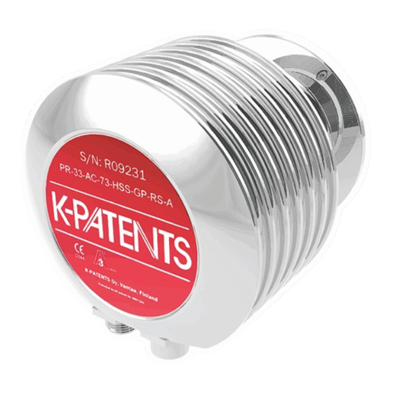
Ethernet connection by using a UDP/IP protocol (see chapter 9). An optional mA output unit is also available, if more than one current output is required. Figure 1.1 K–Patents Sanitary OEM Refractometer PR–33–AC. © Copyright K-Patents 2014. All rights reserved. -
Page 8: Instrument Connections
PR-33-AC instruction manual 2 Instrument connections The instrument has three different connections: power supply (+24 Vdc), 4 – 20 mA cur- rent output, and an Ethernet connection for digital data acquisition and configuration. These connections are grouped into two connectors so that one of the connectors car- ries both the power supply and the current output. -
Page 9: Ethernet Specification
Figure 2.2 shows an example of how to connect three refractometers to an existing LAN with a switch. Ethernet cable Hub/Switch Ethernet cable Figure 2.2 Three refractometers in the same network. © Copyright K-Patents 2014. All rights reserved. -
Page 10: Ip Settings For The Sanitary Oem Refractometer
PR-33-AC instruction manual It is possible to use a WLAN access point to decrease the number of cables (figure 2.3). Access point WLAN Ethernet cable Figure 2.3 Connecting refractometer(s) via wireless. The maximum distance of a single Ethernet connection is 100 m (incl. one joint adapter/coupler), but if longer distances are required, a fiber link may be used to... -
Page 11: Ip Settings For A Stand-Alone Computer
169.254, the IP address of the computer needs to be configured manually to 169.254.23.34, netmask 255.255.0.0. For further troubleshooting, see section 2.3.6. Figure 2.5 Typical IP configuration for a stand-alone laptop when connected to a Sanitary OEM Refractometer; laptop wireless (WLAN) is turned off © Copyright K-Patents 2014. All rights reserved. -
Page 12: Configuring A Network Of Refractometers
PR-33-AC instruction manual Note: The connection will not work if the computer and the refractometer have exactly the same IP address. When the network settings of the instrument (and/or the computer) have been con- figured according to the instructions above, the next step is to test the connection as instructed below in Section 2.3.5. -
Page 13: Troubleshooting The Connection
Enter. If the Ethernet connection is physically working and the ad- dress given to ping is correct, the Sanitary OEM Refractometer will answer to ping and return any data packets sent to it, see figure 2.7. © Copyright K-Patents 2014. All rights reserved. - Page 14 PR-33-AC instruction manual Figure 2.7 Pinging address 169.254.23.33, ping returned fully and connection ok. Document/Revision No. Rev. 1.02 Effective: June, 2014...
-
Page 15: Refractometer Mounting
3.2 Check list for pipe mounting Most Sanitary OEM Refractometers are mounted in a pipe. K-Patents recommends a flow velocity between 1 and 3 m/s (3–10 ft/s). If the flow velocity exceeds 6 m/s (20 ft/s), there is a risk of cavitation. Cavitation may damage the sensor and the piping. - Page 16 PR-33-AC instruction manual IP:169.254.23.33 Figure 3.1 Pipe mounting of Sanitary OEM Refractometer Document/Revision No. Rev. 1.02 Effective: June, 2014...
-
Page 17: Refractometer Wiring
The D-coded female con- nector is for the Ethernet connection. Figure 3.2 Connectors on the Sanitary OEM Refractometer Please see the wiring drawing (figure 3.3) for wiring instructions. © Copyright K-Patents 2014. All rights reserved. - Page 18 PR-33-AC instruction manual Figure 3.3 Wiring drawing Document/Revision No. Rev. 1.02 Effective: June, 2014...
-
Page 19: Startup And Use
(T) values. Both of these values are available on the main page. In addition to these measurements, the refractometer monitors its internal temper- ature and humidity, which both are available on the Diagnostics page. The internal © Copyright K-Patents 2014. All rights reserved. - Page 20 PR-33-AC instruction manual temperature should not be above 65 °C, and the humidity should be below 60 %. High humidity is an indication of leaking seals, and high temperature may deteriorate the measurement performance and/or shorten the lifetime of the unit.
-
Page 21: Instrument Homepage
IP address into the address bar of the computer’s web browser. K-Patents recommends using Firefox 15.0 (or later) or Internet Explorer 8.0 (or later), but most functionality is accessible via any modern web browser. -
Page 22: Main Page
PR-33-AC instruction manual 5.1 Main page Once the instrument homepage has loaded, it will display all the essential information regarding the instrument. Figure 5.1 Main page This page shows the measurement values, serial number and the tag for the instrument. -
Page 23: Parameters
New parameters may be entered into the input fields. Once the parameter editing is done, clicking on the button will apply the designated parameters Submit changes following their confirmation. The parameter update may take a few seconds to apply. © Copyright K-Patents 2014. All rights reserved. - Page 24 PR-33-AC instruction manual Note: If the IP address of the instrument has been changed, the instrument will no longer respond to the factory default address. So check that you are using the correct address for the particular instrument you are trying to access.
-
Page 25: Diagnostics
The optical images produced by the refractometer can be seen on this page. Both the images and the diagnostic values are live values, updated with an interval of a few seconds. Figure 5.3 Diagnostics page © Copyright K-Patents 2014. All rights reserved. -
Page 26: Measuring Field Samples
PR-33-AC instruction manual 5.3.1 Measuring field samples The diagnostics page offers a possibility to measure samples either for field calibration purposes (see section 6.2.2). A sample can be measured by clicking the button on the page. After Field point clicking the button the instrument will measure ten measurement results and shows the average and deviation of the measurements. -
Page 27: Optical Image
Optical image The optical image can be downloaded as a file by clicking on the caption ( Raw optical ) of the image. This file can be used by K-Patents for troubleshooting purposes. image Figure 5.5 Raw optical image © Copyright K-Patents 2014. All rights reserved. -
Page 28: Verification
PR-33-AC instruction manual 5.4 Verification The instrument verification can be performed on this page (figure 5.6). For more infor- mation on the verification procedure, please see chapter 7. Figure 5.6 Verification page Document/Revision No. Rev. 1.02 Effective: June, 2014... -
Page 29: Configuration And Calibration
With both types of damping the residual random noise is inversely proportional to the square root of the damping time. In practice, using a damping time of more than 30 s © Copyright K-Patents 2014. All rights reserved. -
Page 30: Calibrating The Concentration Measurement
PR-33-AC instruction manual does not improve the noise performance. It should also be noted that increasing the damping time will deteriorate the response speed of the instrument. Figure 6.1 shows how the damping time affects the measurement. 6.2 Calibrating the concentration measurement... -
Page 31: The Chemical Curve
The Sanitary OEM Refractometer is shipped with a chemical curve to show the temper- ature compensated Brix value of the process medium. The set of parameters is given by K-Patents and should not be altered, except in case of changing to another process medium. - Page 32 For a more detailed field calibration, send the completed calibration form to either K-Patents headquarters <info@kpatents.com> or your local K-Patents representative. A computer analysis of the data will be made at K-Patents and optimal calibration pa- rameters will be sent to be entered in the system.
-
Page 33: Direct Bias Adjustment
≥21 mA or ≤3.6 mA to indicate diagnostic failures (see figure 6.3). With that informa- tion, it is easier to detect a failure condition on a refractometer, for example, it clearly tells you whether you have an empty pipe or a failed instrument. © Copyright K-Patents 2014. All rights reserved. - Page 34 PR-33-AC instruction manual Measurement Data failure failure 20.5 Figure 6.3 NAMUR NE 43 signal ranges Document/Revision No. Rev. 1.02 Effective: June, 2014...
-
Page 35: Instrument Verification
K-Patents verifies the calibration of all delivered instruments according to a procedure similar to the one described below. The K-Patents quality system is ISO 9001 certified by Det Norske Veritas. -
Page 36: Verification Procedure
Sanitary OEM Refractometer is ±0.0002, then the representative level is the sum of the two accuracy specifications, that is ±0.0004. K-Patents provides a set of standard R.I. liquids, PR-2300, containing five selected liq- uids (1.3300, 1.3700, 1.4200, 1.4700, 1.5200). The set can be ordered from K-Patents. - Page 37 The liquids are automatically detected, and the quality of the measurement is con- stantly monitored throughout the process.If the same liquid is measured several times, new result will replace the older one. A single measurement point can be removed by clicking the button. Remove © Copyright K-Patents 2014. All rights reserved.
- Page 38 Verification page. The temperature should be constant. The sample holder keeps the sample on the prism surface and also blocks the ambient light from reaching the prism. The K-Patents universal sample holder PR-1012 (Fig- ure 7.2) can be used with any K-Patents refractometer.
-
Page 39: Verification Report
Repeat the verification procedure. If the verification still fails, fill in the form Sani- tary OEM Refractometer verification form, found in the end of this manual. You may also print out the verification report, it carries the same information. Send the data to © Copyright K-Patents 2014. All rights reserved. - Page 40 PR-33-AC instruction manual K-Patents or your nearest K-Patents representative and wait <info@kpatents.com> for further instructions. Figure 7.3 The verification report Document/Revision No. Rev. 1.02 Effective: June, 2014...
-
Page 41: Troubleshooting
1. The prism is heavily coated. Remove sensor from line and clean prism manually. 2. There is moisture condensation in the sensor, see Section 8.1.1. 3. The sensor temperature is too high, see Section 8.1.2. © Copyright K-Patents 2014. All rights reserved. -
Page 42: Message Prism Coated
5. There are negative spikes in the optical image. The probable cause is dust or fin- gerprints on the CCD window. Please contact K-Patents. 6. The CCD card in the sensor is faulty. Please contact K-Patents. 8.2.3 Message PRISM COATED Cause: The optical surface of the prism is coated by the process medium or impurities in the process medium. -
Page 43: Concentration Drift During Normal Operation
8.2.2 NO OPTICAL IMAGE 8.2.6 TEMP MEASUREMENT FAULT 8.1.1 HIGH SENSOR HUMIDITY 8.1.2 HIGH SENSOR TEMP 8.2.5 NO SAMPLE 8.2.3 PRISM COATED 8.2.1 OUTSIDE LIGHT TO PRISM 8.2.4 LOW IMAGE QUALITY NORMAL OPERATION © Copyright K-Patents 2014. All rights reserved. -
Page 44: Ethernet Protocol Specification
For this data acquisition, you’ll need to have suitable software on your computer. You can program a data acquisition program yourself following the specifi- cations below. For examples and ready-made applications, please contact K-Patents. 9.1 Communication protocol The communications protocol is based on UDP/IP to port 50023. It is a client/server protocol, where the sensor is the server and thus only sends information when the client (i.e. -
Page 45: Response Format
Note: All the key identifiers (see Section 9.2 for additional information) are case-insen- sitive. However, K-Patents recommends that they are written as in this specification. The server (refractometer) may send the response keys in any order. It will send the mandatory keys (marked with an asterisk in Section 9.2) of the specific request, but it... -
Page 46: Request And Response Errors
PR-33-AC instruction manual 9.1.3 Request and response errors When the server (refractometer) detects an error, it responds with an error message (for more information see Section 9.3). An error message can be caused for example by an unknown request or inability to collect data for the mandatory keys of a response. -
Page 47: Refractometer Information
: float, final concentration value CONC : float, internal temperature Tsens : float, process temperature : float, image shadow edge : float, calculated concentration value CALC : float, quality factor : integer, background light BGlight © Copyright K-Patents 2014. All rights reserved. -
Page 48: Error Message Specification
PR-33-AC instruction manual 9.3 Error message specification If the server (refractometer) does not recognize the request or cannot fulfill it, it re- sponds with an error message. The error message has the following keys: : integer, error code : Unknown request... -
Page 49: Principle Of Measurement
10 Principle of measurement 10 Principle of measurement The K-Patents inline refractometer determines the refractive index n of the process solution. It measures the critical angle of refraction using a yellow LED light source with the same wavelength (589 nm) as the sodium D line (hence n ). - Page 50 PR-33-AC instruction manual Low concentration High concentration Figure 10.2 Optical images The position of the shadow edge is measured digitally using a CCD element (Figure 10.3) and is converted to a refractive index value n by a processor inside the instrument.
-
Page 51: Ec Declaration Of Conformity
EC declaration of conformity... -
Page 52: Sanitary Oem Refractometer Field Calibration Form
Sanitary OEM refractometer field calibration form Fill in this form and fax it to K-Patents Oy or to your local service representative. For contact information, please see <http://www.kpatents.com/> Sensor serial no: Customer: Address: Fax: Email: Sample description: Solvent (water/other): Laboratory method:... - Page 53 1804 CENTRE POINT CIRCLE, SUITE 106 NAPERVILLE, IL 60653, USA TEL. (630) 955 1545 FAX (630) 955 1585 info@kpatents-usa.com K-PATENTS (SHANGHAI CO.,LTD) 17-05H,17F, TIMES SQUARE, NO. 500 ZHANG YANG ROAD PUDONG DISTRICT, SHANGHAI, CHINA TEL+86 21 5178 2775 FAX +86 21 5178 2799...
Need help?
Do you have a question about the PR-33-AC and is the answer not in the manual?
Questions and answers