Table of Contents
Advertisement
Quick Links
Advertisement
Table of Contents
Troubleshooting

Related Manuals for K-Patents PR-23


Summary of Contents for K-Patents PR-23
- Page 1 PROCESS REFRACTOMETER PR-23 INSTRUCTION MANUAL IM-EN-PR23 Rev. 1.91...
- Page 3 Warranty does not cover normal wear and tear of the product over time, or any products that are handled, installed or used against manufacturer’s guidance. Please note that prior to shipping any products or items to K-Patents, a Request for Return Materials Authorization (RMA) must be filled in and submitted to K-Patents Order Handling department.
-
Page 5: Table Of Contents
PR-23 refractometer models ........ - Page 6 5.4.4 Diagnostic values ..........5.4.5 Temperature measurement .
- Page 7 PR-23-AC sensor model code ........79...
- Page 8 PR-23-RP specifications ........
- Page 9 PR-23-SD sensor ........
- Page 10 PR-23 sensor verification form ........
-
Page 11: Introduction
1.1 PR-23 refractometer models The basic system of one or two sensors connected to an Indicating transmitter (DTR) is the same for all PR-23 inline refractometer models. However, there are different sensor models, each model is adapted for different process requirements. -
Page 12: Principle Of Measurement
PR-23 instruction manual 1.2 Principle of measurement The K-Patents inline refractometer sensor determines the refractive index n of the process solution. It measures the critical angle of refraction using a yellow LED light source with the same wavelength (580 nm) as the sodium D line (hence n ). -
Page 13: General Safety Considerations
1 Introduction The position of the shadow edge is measured digitally using a CCD element (Fig- ure 1.4) and is converted to a refractive index value n by a processor inside the sensor. This value is then transmitted together with the process temperature via an interconnecting cable to the Indicating transmitter for further processing, display and transmission. -
Page 14: Warranty
K-Patents is rigorous in ensuring that all products manufactured and supplied by K-Patents shall be free of defects in material and workmanship. K-Patents agrees to ei- ther replace or repair free of charge any product found to be defective, or parts thereof when returned to the nearest authorized K-Patents repair facility within two (2) years of the product’s delivery date. -
Page 15: Inline Refractometer Sensor
2 Inline refractometer sensor 2.1 Sensor description Figure 2.1 below shows a cutaway picture of a PR-23 inline refractometer sensor. The measurement prism (A) is lush mounted to the surface of the probe tip. The prism (A) and all the other optical components are ixed to the solid core module (C), which is springloaded (D) against the prism gasket (B). -
Page 16: Mounting The Sensor
For the Sanitary compact refractometer PR-23-AC see Section 9.3, for the Probe sanitary refractometer PR-23-AP see Section 9.4, for the Process probe refractometer PR-23-GP see Section 9.6, for the Te lon body refractometer PR-23-M and Te lon body semicon refractometer PR-23-MS see Section 9.8 and for the Saunders body refrac- tometer PR-23-W see Section 9.9. -
Page 17: Mounting Guide
2 Inline refractometer sensor 2.2.2 PR-23 mounting guide... -
Page 18: Check List For Pipe Mounting
2.2.4 Check list for mounting in a tank, a vessel or a large pipe A probe sensor PR-23-AP or PR-23-GP can be inserted with a lange or clamp into tanks and vessels which either don’t have a scraper or where the mixer doesn’t touch the vessel wall. -
Page 19: Indicating Transmitter Dtr
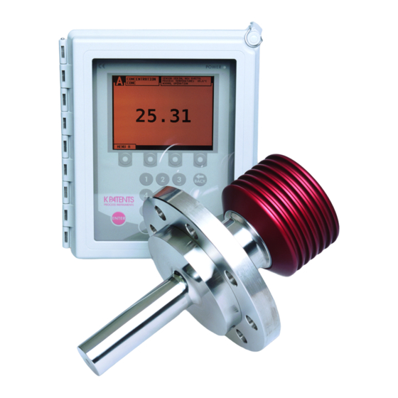
3 Indicating transmitter DTR 3 Indicating transmitter DTR 3.1 Indicating transmitter description The Indicating transmitter DTR is a specialized computer designed to process data received from one or two sensors. The Indicating transmitter enclosure (Figure 3.1) contains a front panel with a backlit Liquid Crystal Display (LCD) and a keyboard. The front panel swings open to give access for connections and service. -
Page 20: Mounting Indicating Transmitter
Figure 3.3. The LCD is best viewed when approximately on the eye level of the user. In sanitary installations, K-Patents recommends using a DTR with stainless steel en- closure. If standard polycarbonate enclosure is used, it should be installed as remotely as practical from the product areas or connections. -
Page 21: Connecting Sensor
3 Indicating transmitter DTR The junction box enables the use of customer’s own cable as long as it meets IEC 61158-2 type A standard requirements, see Section 10.3.2, “Interconnecting cable speci ications”. 3.3.2 Connecting sensor Important: Sensor connector may not be connected or disconnected when the cir- cuits are energized. -
Page 22: Connecting The Indicating Transmitter
PANEL SCREW Figure 3.5 Opening the Front panel of the Indicating transmitter Figure 3.6 The recommended external power switch, K-Patents part nr PR-10900. The ratings of the switch are 10A/230V. Warning! Check that the power is off before opening the Front panel. If the... - Page 23 3 Indicating transmitter DTR completely turn the power off, use the external power switch. The external power switch shall be installed in accordance with the local installation requirements. Figure 3.7 Motherboard of the Indicating transmitter for AC power POWER Figure 3.8 Motherboard of the Indicating transmitter for 24V DC power...
-
Page 24: Power Terminals For Ac Power
PR-23 instruction manual Description of the terminals on the H1 interface card PR-10701 and on the Transmit- ter motherboard PR-10600 (Figure 3.7): On H1 A 1 2 3 Connection for Sensor A, signal wires (1, 2), cable shield (3). B 1 2 3 Connection for Sensor B, signal wires (1, 2), cable shield (3). - Page 25 3 Indicating transmitter DTR reset button, the display will black out for a few seconds. The instrument will be back to full operation within 30 seconds. Reset button Figure 3.9 Location of the reset button...
- Page 26 PR-23 instruction manual...
-
Page 27: Prism Wash Systems
4 Prism wash systems 4 Prism wash systems 4.1 Prism coating Deposit build-up on the prism surface disturbs the measurement. Look out for an abnormally high concentration reading or an upward concentration (CONC) drift. In most applications the prism will keep clean due to the self-cleaning effect. If coating −... -
Page 28: Recommended Wash Pressures And Times
Figure 4.5. Warning! In high pressure wash systems, pressure increase can occur in a closed pipe section when the high pressure pump is operated. K-Patents recommends to mount a pressure relief valve in the pipe section. Relief pressure should be according... - Page 29 4 Prism wash systems Figure 4.1 A prism wash system for steam (non-sanitary)
- Page 30 PR-23 instruction manual Figure 4.2 A sanitary prism wash system for steam...
- Page 31 4 Prism wash systems Figure 4.3 Wiring for a prism wash system for steam...
- Page 32 PR-23 instruction manual Figure 4.4 A prism wash system for high pressure water (non-sanitary)
- Page 33 4 Prism wash systems Figure 4.5 A sanitary prism wash system for high pressure water...
- Page 34 PR-23 instruction manual Figure 4.6 Wiring for a prism wash system for high pressure water...
-
Page 35: Prism Wash Nozzles
For probe refractometers, select the wash nozzle according to wash medium and refractometer model, see Table 4.1 below. Figure 4.9 shows the mounting of the wash nozzle for Sanitary probe refractometer PR-23-AP. Figure 4.10 shows the mounting of the wash nozzle for Process refractome- ter PR-23-GP. Part no. - Page 36 PR-23 instruction manual Figure 4.8 Process connection of a wash nozzle in a flow cell PR-23-AP PR-23-GP Steam nozzle PR-9321 PR-9324 Water nozzle PR-9320 PR-9323 Pressurized water nozzle PR-9322 PR-9325 Table 4.1 Prism wash nozzle selection...
- Page 37 O-ring 10 x 2.5 EPDM K-Patents Tank wall Material General tolerances Scale Join File MTG419.DRW Drawing description Mounting drawing PR-23-AP-RSS-WN/SN/PN Drawn Drawing number 8.11.04 HS MTG419 Appr. 8.11.04 HS Figure 4.9 Mounting of the wash nozzle for Sanitary probe refractometer PR-23-AP...
- Page 38 PR-23 instruction manual Figure 4.10 Mounting of the wash nozzle for Process refractometer PR-23-GP...
-
Page 39: Startup And Use
5 Startup and use 5 Startup and use 5.1 Startup 5.1.1 Initial check 1. Check the wiring, Section 3.3, “Electrical connections”. 2. Connect the power. The Power indicator light (Figure 3.5) and the screen should light up within a few seconds. 3. -
Page 40: Calibration Check
PR-23 instruction manual 6. For a connected sensor, the diagnostic message at start-up should be NORMAL OPERATION or, if the process pipe is empty, . Otherwise, see Section 8.4, “Diagnostic NO SAMPLE messages table”. 7. The TEMP value should show the current process temperature. -
Page 41: Keyboard Functions
5 Startup and use 5.2.1 Keyboard functions Number keys: The 10 number keys, minus sign, and decimal point are used to enter numerical parameters. They are also used for menu selections. ENTER key: The ENTER key is used to implement the selected (highlighted) menu command or to accept an entered value. - Page 42 PR-23 instruction manual Figure 5.3 Display setup menu Main display format: As you can see in Figure 5.1, there are four different Main dis- play formats: the dual sensor format shows information on both sensors while the three different single sensor formats show selected information on one sensor at a time.
-
Page 43: Viewing System Information
5 Startup and use the DTR. The default language is English and it is always available. The order and number of the languages in the language menu varies depending on what languages are loaded into the DTR. Language change through this menu is immediate. 5.3 Viewing system information selection from the Main menu (Figure 5.2) opens a path to complete DESCRIPTION... -
Page 44: Viewing Sensor Status
SENSOR STATUS 5.4.1 Optical image There are two different image detection algorithms in the PR-23. The original image detection algorithm has been complemented with an advanced IDS (Image Detection Stabilization) algorithm which compensates for some unwanted noise in the image. -
Page 45: Optical Image With Vd
In the example, only the right edge is visible. 5.4.3 Optical image with VD A PR-23-GP can be ordered with option -VD, Vertical Borderline Image Detection. This is typically used in a sugar vacuum pan. With vertical borderline the optical image is without IDS, and the sides of the optical image are straight and slightly sloping. -
Page 46: Diagnostic Values
PR-23 instruction manual 5.4.4 Diagnostic values − The values at the left of the graph are used for diagnostic purposes: − is the inal concentration value including Field calibration adjustment, see CONC − Figure 6.12. − , see Section 5.4.5. -
Page 47: Sensor Verification
5 Startup and use 5.5 Sensor verification A company maintaining quality system according to ISO 9000 quality standards must have de ined procedures for controlling and calibrating its measuring equipment. Such procedures are needed to demonstrate the conformance of the inal product to speci ied requirements. - Page 48 PR-23 instruction manual...
-
Page 49: Configuration And Calibration
(see upper edge of the display to check which sensor is currently chosen and switch in the Outputs display if necessary). The PR-23 offers three types of signal damping. The damping parameter is set sep- arately through the Outputs menu selected from the Calibration menu by 2 OUTPUTS What the damping time means in practice depends on the damping type. -
Page 50: Linear Damping
PR-23 instruction manual 6.1.2 Linear damping If the process has fast step changes, linear (fast) damping gives shorter settling time. In the linear damping (fast damping), the output is the running average of the signal during the damping time. After a step change the signal rises linearly and reaches the inal value after the damping time. -
Page 51: External Hold
6 Configuration and calibration 0.5 /s 0.2 /s 0.05 /s 90 100 110 120 Time [s] Figure 6.3 Slew rate damping 1. By using an external hold switch (see Section 6.3.2) 2. During prism wash (see Section 6.5.2) 3. For a preprogrammed time when there is an intermittent loss of sample on the prism (due to voids in the process) When the measurement result is in hold, the displayed concentration value and mA output do not change. -
Page 52: Tolerance Time
PR-23 instruction manual 6.2.3 Tolerance time The tolerance time setting can be used in processes where there are intermittent breaks in the measurement due to non-representative sample on the prism. This typ- ically occurs when there are large voids in the process liquid. -
Page 53: Hold Source Interactions
6 Configuration and calibration de ined tolerance time (see Section 6.2.3 for tolerance time). By default the QF thres- hold value is -500. 6.2.5 Hold source interactions There are three different reasons why the measurement signal may be in hold. All three result in the same behaviour, but they also interact with each other. -
Page 54: Hold Functions With
PR-23 instruction manual 6.2.7 Hold functions with DD-23 The K-Patents Digital Divert Control System DD-23 uses the displayed concentration value in its decision logic. Due to this, the external hold functionality must not be used with a DD-23, as it could potentially render the system unsafe by freezing the measurement result. - Page 55 6 Configuration and calibration Figure 6.6 Relay menu for Relay 1 Closed contact if there is no equipment mal- FUNCTION INSTRUMENT OK function. See also Section 8.4 on page 75. Used as alarm relay, closing contact if source FUNCTION LOW LIMIT value is below set limit.
-
Page 56: Configuring Input Switches
PR-23 instruction manual Figure 6.7 The manual set display for relays 6.3.2 Configuring input switches For the electrical properties of the four input switches, see Section 3.3. To see which switches are closed, check the Description menu, see Section 5.3. To con igure the switches, follow the instructions below: 1. -
Page 57: Configuring Ma Outputs
6 Configuration and calibration Figure 6.9 Arrival to Switch 1’s sensor selection menu, sensor A selected process stops (as indicated by contact closure).The wash is repeated when the process restarts (if the stop lasts over 60 seconds). The signal is on hold between washes.When used with an external independent timer, contact closure holds the output signal. - Page 58 PR-23 instruction manual − First select in the Main menu and enter password if necessary. 5 CALIBRATION − Then select in the Calibration menu. In the Outputs menu, select 2 OUTPUTS 5 mA OUTPUTS Select the mA output, 1 or 2, to get to the Output menu (Figure 6.10 below) where the output can be con igured.
-
Page 59: Calibrating The Concentration Measurement
TEMP in Centigrade. Hence, the calibrations of all PR-23 sensors are identical, which makes sensors inter- changeable. Furthermore, the calibration of each sensor can be veri ied using stan- dard refractive index liquids, see Chapter 13. -
Page 60: The Chemical Curve
A chemical curve is speci ic to the given process medium, e.g. sucrose or sodium hy- droxide. The set of parameters is given by K-Patents and should not be altered, except in case of changing to another process medium. The parameters can be changed by... -
Page 61: Field Calibration
Record the calibrating data on the PR-23 ield calibration form (found in the end of this manual), also available at <http://www.kpatents.com/> and by emailing a request to <info@kpatents.com>. -
Page 62: Entering Field Calibration Parameters
Thus calibration using the process liquid should always be made inline. 6.4.4 Entering field calibration parameters The ield calibration parameters supplied by K-Patents are entered by selecting from the Main menu, followed by irst CALIBRATION 1 CHEMICAL &... -
Page 63: Wash Cycle
6 Configuration and calibration 6.5.1 Wash cycle The wash logic is shown in Figure 6.15 as a low diagram. The automatic prism wash cycle (Figure 6.14) consists of three phases: precondition, wash and recovery. The op- tional preconditioning function is used to e.g. blow out the condensate before wash- ing. - Page 64 PR-23 instruction manual Preventing automatic wash: The preconditioning and wash relays are never activated by the automatic wash con- − trol: Under the diagnostic message (see Section 8.2.6) as this indicates a NO SAMPLE − clean prism in an empty process line. The diagnostic message is...
- Page 65 6 Configuration and calibration NOTES 1. Remote wash is triggered at The other the closing of the switch. If sensor the switch is held closed, washing? only one wash cycle is carried out. 2. The wash is inhibited if there is no sample, no sensor or the sensor cannot MANUAL measure correctly.
- Page 66 PR-23 instruction manual Precondition enabled? Precondition 1 s wait Start washing Wash auto-cut enabled? nD < nD limit? Wash time reached? Wash time reached? Stop washing Recovery Figure 6.16 Wash cycle...
-
Page 67: Setting Prism Wash Parameters
6 Configuration and calibration 6.5.2 Setting prism wash parameters To set the prism wash parameters for a given sensor, irst select the sensor, then select from the Main menu, and then . This menu contains the 5 CALIBRATION 4 PRISM WASH alternatives (factory settings are given in parentheses): 0–30 s (0 s) PRECONDITION TIME... - Page 68 PR-23 instruction manual To set a low temperature limit, choose and enter the temper- 8 TEMP LIMIT VALUE °C ature (in °C!) where the limit should be. The empty pipe check prevents washing if message is , i.e. there’s no NO SAMPLE process liquid in the pipe.
-
Page 69: Regular Maintenance
If your refractometer has prism wash, check that it works, see Section 5.1.3. 7.1 Checking the sensor humidity level The PR-23 sensor head has an internal humidity detector. The humidity reading can be checked on the Indicating transmitter display, select... -
Page 70: Disassembling The Sensor
Safe-Drive™ system designed for safe sensor removal during process). 7.3.1 Disassembling the sensor The letters in the text refer to Figure 7.1. The instructions are valid for all PR-23 mod- els. 1. Remove the sensor from the process line and rinse it well. -
Page 71: Replacing The Dryer
7 Regular maintenance 7.3.2 Replacing the dryer 1. Follow the instructions in Section 7.3.1. 2. Place the sensor cover (D) with the bus terminator card (F) upwards. 3. Open ive hexagon socket screws holding the bus terminator card (F) and remove the card. - Page 72 PR-23 instruction manual Figure 7.3 Removal of prism 9. Remove prism support (b) kept by two ISO 7380-1 A4 M3x10 TX-10 screws (c). 10. Remove old prism gasket (d). 11. To remove the prism (e), push it gently against the springs machined into the prism plate (f), as indicated by an arrow in Figure 7.4.
- Page 73 7 Regular maintenance Figure 7.4 The prism and prism plate 16. Tighten the screws (c) to the bottom. Important: Make sure you are using the original round-headed screws. 17. Check that the temperature element (a) is properly spring-loaded. In outer posi- tion, the sensor tip should be level with the prism sensor, Figure 7.5.
- Page 74 PR-23 instruction manual Figure 7.6 Tightening the spring holders 21. Clean the window of the CCD element. Attach the CCD card (L) to the core module (S) by the three spacer screws. 22. Attach the sensor processor card (E) with the three hexagon socket screws. Con- nect the ribbon cable (H), the LED connector, and the temperature element screw terminal.
-
Page 75: Troubleshooting
8 Troubleshooting 8 Troubleshooting 8.1 Hardware To troubleshoot refractometer hardware problems, it is often important to localize the different cards inside the DTR. The Diagnostic LEDs on the cards help solve the problems and give an indication on whether a connection is good. Figure 8.1 Positions of the transmitter cards Figure 8.2 Motherboard PR-10600 and H1 interface card PR-10701 in detail. -
Page 76: Blank Display
PR-23 instruction manual 8.1.1 Blank display Is Power indicator light on? Processor See figure on next page to Power supply card LEDs troubleshoot power supply. problem blinking? Processor card PR-10500 or Front panel bad. Processor Processor card card LEDs PR-10500 bad. - Page 77 8 Troubleshooting Important safety considerations +24 V Always switch off the mains before Power supply OK disconnecting or reconnecting cables, modules, etc. Beware of the high voltage terminals 34 and 35 Mains Have it fixed Measuring instructions Use a DMM (Digital Multimeter) to measure the voltage Measure the +24 V from terminals Disconnect +24 V from...
-
Page 78: Diagnostic Leds
PR-23 instruction manual 8.1.2 Diagnostic LEDs Figure 8.1 and Figure 8.2 assist to localize the diagnostic LEDs. Status Indication Front panel green LED DTR power is on; 8.1.1 Processor card PR-10500 is active. Transmitter processor card PR-10500 2 yellow LEDs blinking Processor card ok. -
Page 79: Display Unreadable
8 Troubleshooting Important: A lit red LED on PR-10701 always indicates a problem. Red LEDs are always turned off in normal operation, whether any sensors are connected or not. Transmitter processor card POWER DISPLAY 24 V/3 V KEYBOARD 3 V DC 24 V DC Power supply module... -
Page 80: Message No Sensor
PR-23 instruction manual 8.1.4 Message NO SENSOR Cause: The current in the cable to this sensor is below 20 mA. Normally this means that there’s no sensor connected to the cable or that there’s no cable to the DTR. If this message comes up while a sensor properly is connected, the most likely cause of this message is a fault in the sensor. -
Page 81: Message High Sensor Humidity
8 Troubleshooting 8.1.7 Message HIGH SENSOR HUMIDITY Tells that humidity measured at the Sensor processor card exceeds 60 % relative hu- midity. The reason may be moisture leaking in through prism seal or the cover being open. If the sensor cover has been off for a long time, see Section 7.3.2 “Replacing the dryer”. -
Page 82: Measurement
PR-23 instruction manual 8.2 Measurement 8.2.1 Message OUTSIDE LIGHT ERROR Cause: The measurement is not possible because too much outside light reaches the camera. Action: Identify the light source (for example sun shining into an open tank or a translucent pipe) and block the light from getting to the prism at the sensor tip. -
Page 83: Message Outside Light To Prism
Section 7.3.3 “Replacing the prism and prism gaskets”. Note: The prism gasket must be replaced, too. Note: A difference to some other process temperature measurement is not a fault. PR-23 measures the true temperature of the prism surface. 8.2.8 Concentration drift during NORMAL OPERATION For drift upward, suspect prism coating, Section 4.1, “Prism coating”. -
Page 84: Wash
PR-23 instruction manual 8.3 Wash 8.3.1 Message EXTERNAL HOLD The concentration measurement is on HOLD due to an external switch closure. For explanation, see Section 6.3.2, “Con iguring input switches”. − 8.3.2 Messages PRECONDITIONING WASH RECOVERING − : An optional preconditioning relay is closed, see Section 6.5 PRECONDITIONING −... -
Page 85: Diagnostic Messages Table
8 Troubleshooting 8.4 Diagnostic messages table Important: The messages are listed in descending order of priority. Example: If both are activated, only NO OPTICAL IMAGE TEMP MEASUREMENT FAULT NO OPTICAL will be shown. The wash related messages have priority only during the wash IMAGE cycle (preconditioning–wash–recovery). - Page 86 PR-23 instruction manual...
-
Page 87: Sensor Specifications
9 Sensor specifications 9 Sensor specifications Note: For the speci ications of the PR-23-SD sensor for K-Patents Safe-Drive™ system, see Sections 11.2 and 10.4. Figure 9.1 Sensor nameplates 9.1 Sensor compatibility Electrically: All the K-Patents PR-23 refractometer sensors are interchangeable. The PR-23 sensors are not interchangeable with the PR-01 and PR-03 range sensors. -
Page 88: Sanitary Process Refractometer Pr-23-Ac
(74) and with a standard prism (62) 9.3 Sanitary process refractometer PR-23-AC The refractometer PR-23-AC is a 3A Sanitary process refractometer for measuring concentrations in a pipe line. Easy to install in any pipe size directly or using a lowcell. -
Page 89: Pr-23-Ac Sensor Model Code
9 Sensor specifications 9.3.1 PR-23-AC sensor model code SANITARY COMPACT REFRACTOMETER for pipelines Model and description Model PR-23 = Refractometer PR-23 Sensor model -A = 3-A Sanitary Standard 46-03 certified Sensor type C = Compact type for pipeline installations Refractive index range limits -62 = R.I. -
Page 90: Pr-23-Ac Mounting Hardware Model Code
PR-23 instruction manual 9.3.2 PR-23-AC mounting hardware model code Elbow flow cells for PR-23-AC-62-HSS sensor Model and description Model AFC = Elbow flow cell Sensor connection -H = Sanitary 3A-clamp, 2½ inch Material of construction SS = AISI 316 L... - Page 91 -EH = EHEDG Type EL Class I Certified Model Polishing option -EP = Electropolished process wetted parts (RA 0.38µm, 15 µ inch) Elbow flow cells with prism wash nozzle for PR-23-AC-63-HSS Model and description Model AFC = Elbow flow cell Sensor connection -H = Sanitary 3A-clamp, 2½...
- Page 92 PR-23 instruction manual Mounting hardware for PR-23-AC-62-HSS sensor Model and description Model MFC = Mini Flow Cell Sensor connection -H = Sanitary 3A-clamp, 2½ inch Material of construction SS = AISI 316 L Process connection -H = Sanitary 3A-clamp Pipe section diameter 05 = 15 mm (½...
- Page 93 9 Sensor specifications Side Flow Cells, connection Sanitary 3A-Clamp 2½ inch Model and description Model SFC = Side Flow Cell (A) Sensor connection -HH = Sanitary 3A-clamp, 2½ inch Material of construction SS = AISI 316 L Process connection -H = Sanitary 3A-clamp Pipe section diameter 10 = 25 mm (1 inch) 15 = 40 mm (1½...
-
Page 94: Pr-23-Ac Specifications
PR-23 instruction manual 9.3.3 PR-23-AC specifications General speci ications Refractive Index range: Full range n 1.3200–1.5300 (corresponds to hot water – 100 Brix) Accuracy: Refractive index n ± 0.0002 (corresponds typi- cally to ± 0.1 % by weight) Repeatability and stability correspond to accuracy... -
Page 95: Pr-23-Ac Parts List
2.5” Sanitary clamp PR-9202 2.5” Sanitary gasket EPDM PR-9203 2.5” Sanitary gasket NBR PR-9204 2.5” Sanitary gasket PTFE (Teflon®) PR-10001 PR-23 H head (3A sanitary clamp connection) PR-10021 PR-23 E head (Varivent®connection) PR-10048 68x3 O-ring Alignment pin PR-10005 PR-23 base Item Pcs. -
Page 96: Pr-23-Ac Mounting Specifics
PR-23 instruction manual 9.3.5 PR-23-AC mounting specifics K-Patents sanitary process refractometer PR-23-AC is connected to the process by a 2 1/2" 3A sanitary clamp. The recommended mounting is in a pipe bend, with a ver- tical low upwards before the sensor, and a horizontal pipe after. By this mounting is obtained 1. - Page 97 Customer Figure 9.5 Flowcell AFC-HSS- Sanitary gasket 1"/1.5" EPDM Customer Sanitary clamp 1"/1.5" AISI304 Customer PR-03-A/PR-23-AC sensor K-Patents H10 for pipe diameter 1" (25 mm) and H15 for pipe diameter 1 1/2" (40 mm) Rev. Date Rev. by Appr. Mark...
- Page 98 PR-23 instruction manual SECTION A-A SCALE 1 : 2 Flow cell type 48.6 51.6 89.0 AFC-HSS-H20-SI 48.6 48.6 51.6 89.0 AFC-HSS-H20-RI 35.6 60.3 64.1 108.0 AFC-HSS-H25-SI 60.3 Figure 9.7 Flowcell AFC-HSS- H20 for pipe diameter 2" (50 mm) and H25 for pipe diameter 2 1/2" (65 mm)
-
Page 99: Pr-23-Ac I-Line Fitting
PRE.01 Appr. 07.08.2013 AHä K-Patents offers certain PR-23-AC con igurations which have been certi ied to ful ill the sanitary requirements published by EHEDG (European Hygienic Engineering & Design Group) organization. During this certi ication the hygienic characteristics of both the refractometer and the process connection were evaluated against the applic- able requirements. -
Page 100: Sanitary Probe Refractometer Pr-23-Ap
K-Patents offers a 3A Sanitary Standard Accepted repair and maintenance package in which all wetted parts, prism, gaskets and dryer are replaced. Note that this repair service can be completed only by a 3A authorized service center (K-Patents factory or regional headquarters). - Page 101 (E) Requires mount adaptor VFME-23-VSS or VFMF-23-VSS, design according to Sanitary 3-A (F) Available with STR-Indicating transmitter and IS isolator only (G) For connections -T, -N, -I, -R, -S, -H, -C SANITARY PROBE REFRACTOMETER PR-23-AP with prism wash for large pipelines and vessels Model and description Model...
-
Page 102: Pr-23-Ap Mounting Hardware Model Code
Part number and description Part no. VFMA-23-PSS = Tank bottom flange for PR-23-AP, MT4 DN 25/1T VFMA-23-PSS VFBP-23-PSS = Tank bottom blind flange for PR-23-AP, MT4 DN 25/1T VFBP-23-PSS VFME-23-VSS = Mount adaptor for PR-23-AP-62-VSS HEXNUT type VFME-23-VSS VFMF-23-VSS = Mount adaptor for PR-23-AP-62-VSS HEXNUT extended... - Page 103 -090 -180 = Straight pipe, 180 degrees -180 (A) Includes one 2½ inch blind flange with 2½ inch EPDEM gasket and 2½ inch sanitary clamp Aseptic Steam Valve for PR-23-AP-ISS Model and description Model ASV = Aseptic Steam Valve Sensor connection -H = Sanitary 3A-clamp, 2½...
-
Page 104: Pr-23-Ap Specifications
PR-23 instruction manual 9.4.3 PR-23-AP specifications General speci ications Refractive Index range: Full range n 1.3200–1.5300 (corresponds to hot water – 100 Brix) Accuracy: Refractive index n ± 0.0002 (corresponds typ- ically to ± 0.1 % by weight) Repeatability and stability correspond to accu-... -
Page 105: Pr-23-Ap Parts List
9 Sensor specifications 9.4.4 PR-23-AP parts list Item Pcs. Part No. Description PR-9205 2.5” sanitary ferrule VFMA-23-PSS MT4 DN25/1T APV tank bottom flange PR-4275 4” sanitary ferrule PR-9201 2.5” sanitary clamp PR-9270 4” sanitary clamp PR-9202 2.5” sanitary gasket EPDM PR-9203 2.5”... -
Page 106: Pr-23-Ap Mounting Specifics
K-Patents probe refractometer, types PR-23-AP-T is connected to the process by a 2 1/2" 3A sanitary clamp, Figure 9.10. PR-23-AP-R is connected by 4" sanitary clamp. Note: For higher process (or ambient) temperatures, use instead a lush mounted sensor, where the electronics in the sensor head are farther away from the process heat, Figure 9.11. -
Page 107: Pr-23-Ap I-Line Fitting
Sensor wetted parts material is AISI 316L or Hastelloy C, gaskets EPDM. 9.4.7 Mounting specifics for EHEDG certified PR-23-AP configuration K-Patents offers certain PR-23-AP con igurations which have been certi ied to ful ill the sanitary requirements published by EHEDG (European Hygienic Engineering &... -
Page 108: Sanitary Standard Compliance
K-Patents offers a 3A Sanitary Standard Accepted repair and maintenance package in which all wetted parts, prism, gaskets and dryer are replaced. Note that this repair service can be completed by 3A authorized service center only (K-Patents factory or regional headquarters). - Page 109 9 Sensor specifications Wafer flowcell model code MODEL AND DESCRIPTION MODEL WFC = Wafer flowcell Sensor connection -K = Sandvik L coupling 76.1 mm (insertion length 12 mm) Construction material -SS = AISI 316 L -HA = Alloy 20 -HC = Hastelloy C / ASTM C276 HC -NI = Nickel 200 -TI Titanium ASTM B248 -SU = AISI 904L (A)
-
Page 110: Pr-23-Gc Specifications
PR-23 instruction manual 9.5.2 PR-23-GC specifications General speci ications Refractive Index range: Full range n 1.3200–1.5300 (corresponds to 0–100 % b.w.), Sapphire prism Accuracy: Refractive index n ± 0.0002 (corresponds typ- ically to ± 0.1 % by weight) Repeatability and stability correspond to accu-... -
Page 111: Pr-23-Gc Parts List
Screw M4x30 DIN 912 A4 Disc spring PR-10002 O-ring seal 82x3 Disc spring holder PR-10047-SC PR-23 endplate with label and screws PR-10031 O-ring seal 89.5 x 3 Screw M4x8 DIN 964 A4 PR-10032 O-ring seal 24 x 2 Cable gland M16x1.5... -
Page 112: Pr-23-Gc Mounting Specifics
PR-23 instruction manual 9.5.4 PR-23-GC mounting specifics The Compact refractometer is mounted either in a pipe elbow by a Sandvik coupling connection or in a straight pipe via a Wafer low cell or a Pipe low cell. Both low cell mounting designs create optimum low velocity on the measurement surface pro- viding a good self-cleaning effect. - Page 113 9 Sensor specifications Figure 9.13 Mounting the sensor in a 2" pipe Figure 9.14 Mounting the sensor with a pfc flow cell...
- Page 114 PR-23 instruction manual Figure 9.15 Mounting the sensor with a wfc flow cell...
- Page 115 9 Sensor specifications Use gasket material appropriate to the process media Use PTFE Teflon tape for all threaded connections Figure 9.16 Mounting the Wafer flow cell and sensor in a vertical pipe...
- Page 116 PR-23 instruction manual Use gasket material appropriate to the process media Use PTFE Teflon tape for all threaded connections Figure 9.17 Mounting the Wafer flow cell and sensor in a horizontal pipe...
-
Page 117: Probe Process Refractometer Pr-23-Gp
9 Sensor specifications 9.6 Probe process refractometer PR-23-GP The K-Patents Probe process refractometer PR-23-GP is a general industry model for measuring liquid concentrations in various in-line applications, like chemicals, ibers, plastics, salts and sodium components. It is typically installed in large pipes and ves- sels. -
Page 118: Pr-23-Gp Specifications
PR-23 instruction manual 9.6.2 PR-23-GP specifications General speci ications Refractive Index range: Full range n 1.3200–1.5300 (corresponds to hot water – 100 Brix) Accuracy: Refractive index n ± 0.0002 (corresponds typ- ically to ± 0.1 % by weight) Repeatability and stability correspond to accu-... -
Page 119: Pr-23-Gp Parts List
9 Sensor specifications 9.6.3 PR-23-GP parts list Item Pcs. Part No. Description PR-10009 PR-23-GP-L head PR-10010 PR-23-GP-D head PR-10011 PR-23-GP-D-NC head ANSI 3” 150 lbs flange DIN 80 PN 25 flange JIS 80A 10k flange Item Pcs. Part No. Description... -
Page 120: Pr-23-Gp Mounting Specifics
Customer’s pipe <2” Customer’s pipe <2” Centering hole Centering hole 0.787 0.787 20.0 20.0 Customer’s pipe <2” Customer’s pipe <2” Figure 9.18 PR-23-GP-A/D/JSS Y flowcell Model Model 26.7 [1.051] 26.7 [1.051] 108 [4.252] 108 [4.252] PFC-23-GP-ASS-A10-NC PFC-23-GP-ASS-A10-NC 190.5 [7.5] 190.5 [7.5]... - Page 121 9 Sensor specifications Customer’s pipe Customer’s pipe 0.787 0.787 Customer’s pipe Customer’s pipe Figure 9.20 PR-23-GP-LSS Y flowcell 25 [1] 25 [1] 125 [6.102] 125 [6.102] PFC-23-GP-LSS-D20-NC PFC-23-GP-LSS-D20-NC PFC-23-GP-LSS-J20-NC PFC-23-GP-LSS-J20-NC 51 [2] 51 [2] 155 [6.102] 155 [6.102] Figure 9.21 PR-23-GP-LSS flowcell...
-
Page 122: Process Refractometer Pr-23-Rp
PR-23 instruction manual 9.7 Process refractometer PR-23-RP K-Patents Process Refractometer PR-23-RP is a heavy-duty re inery model that is de- signed to support the unique requirements of the re ining and petroleum industries. Typical applications are in accurate liquid concentration mesurements, e.g. acid in alkylation, glycol or amines in gas processing and multi-product (crude oil, fuel oil, diesel) interfaces in transfer operations. -
Page 123: Pr-23-Rp Specifications
9 Sensor specifications 9.7.2 PR-23-RP specifications General speci ications Refractive Index range: Full range n 1.3200–1.5300 (corresponds to hot water – 100 Brix) Accuracy: Refractive index n ± 0.0002 (corresponds typ- ically to ± 0.1 % by weight) Repeatability and stability correspond to accu-... -
Page 124: Pr-23-Rp Parts List
PR-23 instruction manual 9.7.3 PR-23-RP parts list Item Pcs. Part No. Description PR-10043 PR-23-RP-SS head PR-10043-HC PR-23-RP-SS Hastelloy® C 276 Item Pcs. Part No. Description PR-10043-HA PR-23-RP-SS Alloy® 20 head PR-10103 Sensor processor card PR-10048 68x3 O-ring Screw M3x6 DIN 912 A2... -
Page 125: Pr-23-Rp Head Parts List
9 Sensor specifications REV. DESCRIPTION DATE APPR. 30.3.2012 Code changed, PR-numbers added 6.6.2012 9.7.4 PR-23-RP head parts list Torque 6Nm (4,4 lbs/ft) PR-10043 Item Pcs. Part No. Description Item Pcs. Part No. Description PR-10043-HC PR-10043-HA PR-23-RP head 2” ANSI 300 flange... -
Page 126: Pr-23-Rp Dimensions
PR-23 instruction manual 9.7.5 PR-23-RP dimensions Figure 9.22 PR-23-RP-73-M20... -
Page 127: Pr-23-Rp Mounting Specifics
2 inch or larger pipes or vessels, or via a 1 inch, 2 inch or 3 inch cross lowcell. Due to the sensor’s rugged, innovative non-weld sensor body, and self- cleaning or optional wash system capabilities, the PR-23-RP functions accurately and reliably in harsh re inery conditions. Intrinsically safe and hazardous area certi ica-... - Page 128 PR-23 instruction manual PR-23-RP mounting in CFC 1” line Figure 9.23 CFC-RP-M20-SS/HC/HA-M10-NC-PG/SN/WP flowcell Item. Description Supplied by Pcs. Item. Description Supplied by Pcs. Sensor PR-23-RP-73-M20 K-Patents Bolt, washer and nut for 1”flange Customer CFC-RP-M20-M10-NC-PG/SN/WP K-Patents 1’’ flange gasket Customer 2”ANSI 300 Wash nozzle K-Patents 2’’...
- Page 129 9 Sensor specifications PR-23-RP mounting in 2” line Figure 9.24 CFC-RP-M20-SS/HC/HA-M20-NC-PG/SN/WP flowcell Item. Description Supplied by Pcs. Item. Description Supplied by Pcs. Sensor PR-23-RP-73-M20 K-Patents 2”flange gasket Customer CFC-23-RP-M20-M20-NC-PG/SN/WP K-Patents 2”ANSI 300 Welding neck flange Customer 2’’ ANSI 300 Wash nozzle K-Patents Bolt, washer and nut for 2”flange...
-
Page 130: Pr-23-Rp Prism Wash System
PR-23 instruction manual 9.7.7 PR-23-RP prism wash system A prism wash system is available for the PR-23-RP. This requires the use of a CFC- RP-M20 low-cell in combination with a 2” ANSI 300 CFC wash nozzle. Both of these components are available from K-Patents. All the further components speci ically re- quired for the wash system installation, are obtained independently by the customer. -
Page 131: Teflon Body Refractometer Pr-23-M/Ms
9 Sensor specifications 9.8 Teflon body refractometer PR-23-M/MS K-Patents Te lon body refractometer PR-23-M/MS is designed for use in chemically aggressive solutions and ultra-pure ine chemical processes. PR-23-M is an all-purpose model, PR-23-MS is designed especially for the semicon- ductor industry. The sensor has a built-in lowcell designed to keep all metal and other easily corroding parts from coming into contact with the process liquid. -
Page 132: Pr-23-M Sensor Model Code
PR-23 instruction manual 9.8.1 PR-23-M sensor model code MODEL AND DESCRIPTION MODEL PR-23 = Sensor PR-23 Sensor model -M = Aggressive medium adapter Refractive Index range limits 73 = n 1.320–1.530 (0–100 Brix) Sapphire prism 74 = n 1.260–1.470 Sapphire prism... -
Page 133: Pr-23-M Specifications
Te lon body sensor model for aggressive medium Sensor protection class: IP67, Nema 4X Sensor weight: 5.0 kg (12.1 lbs) FLOW CELL FOR PR-23-M Process connection: Thread G 1/2" or 1/2" NPT female Process pressure: max. 10 bar (145 psi) Process temperature: max. -
Page 134: Pr-23-M Parts List
Pcs. Part No. Description Item Pcs. Part No. Description Screw M5x60 DIN 7991 A4 PR-10036 PR-23 compact sensor CORE module PR-23-M endplate PR-9011 Thermal conductor PR-9129 PR-03/23-M protection cover PR-9010 Disc spring set Screw DIN 912 M4x10 A4 Disc spring... -
Page 135: Pr-23-Ms Sensor Model Code
025 = 1/4 inch -025 050 = 1/2 inch -050 075 = 3/4 inch -075 100 = 1 inch -100 Flowcell wetted parts material -TM = Modified PTFE Ultra-Pure (PTFE=Polytetrafluoroethylene) Flowcell is integrally mounted to the PR-23-MS sensor Example: Flowcell: F2-025-TM... -
Page 136: Pr-23-Ms Specifications
Te lon body sensor model for aggressive medium Sensor protection class: IP67, Nema 4X Sensor weight: 5.0 kg (12.1 lbs) FLOW CELL FOR PR-23-MS Process connection: Thread G 1/2" or 1/2" NPT female Process pressure: max. 10 bar (145 psi) Process temperature: max. -
Page 137: Pr-23-Ms Parts List
Screw M4x30 DIN 912 A4 PR-10005-EC PR-23-EC base PR-10002 O-ring seal 82x3 Screw M5x12 DIN 912 A2 Cable gland M16x1.5 Locking spacer M5 PR-23-M nameplate PR-10036 PR-23 compact sensor CORE module Screw M4x8 DIN 964 A4 PR-9011 Thermal conductor O-ring seal 89.5 x 3... -
Page 138: Pr-23-M/Ms Mounting Specifics
PR-23 instruction manual 9.8.7 PR-23-M/MS mounting specifics K-Patents Te lon body refractometer PR-23-M/MS is connected to the process by a G1/2" female or a 1/2" NPT process connection, Figure 9.27 below. Important: Always install PR-23-M/MS with sensor support to prevent the sensor weight from pulling at the non-metallic piping. -
Page 139: Saunders Body Refractometer Pr-23-W
PFA/ETFE lining ensures the chemical resistance. The sensor itself is built just like the PR-23-M sensor (see Section 9.8) and it is ixed to the Saunders body in the same way, with a sapphire plate and a Kalrez O-ring to keep all the metallic parts away from the process liquid. -
Page 140: Pr-23-W Sensor Model Code
-IA = ATEX and IECEx certified EX II 1 G Ex ia II C T4 Ga (up to Zone 0) Sensor housing -SC = Stainless steel Example: Sensor: PR-23-W62-2TF4-GP-SC SAUNDERS VALVE BODY FOR SENSOR PR-23-W MODEL SVB = Saunders valve body Process line connection -A040 = ANSI flange 4 inch 150 lbs -A040... -
Page 141: Pr-23-W Specifications
9 Sensor specifications 9.9.2 PR-23-W specifications General speci ications Refractive Index range, stand.: Full range n 1.3200–1.5300 (0–100 Conc% b.w.) with Spinel prism H62 and Sapphire prism H73 Refractive Index range, option: 1.2600–1.4700 with Sapphire prism H74 Accuracy: Refractive index n ±... -
Page 142: Pr-23-W Parts List
PR-23 cover PR-10005 PR-23 base Screw M4x30 DIN 912 A4 Screw M5x12 DIN 912 A2 Cable gland M16x1.5 Locking spacer M5 PR-10002 O-ring seal 82x3 PR-10012 PR-23 compact sensor CORE module PR-23-W nameplate PR-9011 Thermal conductor Screw M4x8 DIN 964 A4... -
Page 143: Pr-23-W Mounting Specifics
9 Sensor specifications 9.9.4 PR-23-W mounting specifics PR-23-W Saunders valve body lowcell can be mounted either vertically or horizon- tally. Special sensor support is not needed as the valve body (piping) supports the sensor. Either way sensor cover should always be horizontal to avoid sedimentation or gas/air pocket on the prism. -
Page 144: Process Refractometers In Potentially
Essential Health and Safety Requirements is assured by complying with standard EN 50 021:1999. The PR-23-...-AX refractometers have been certi ied by DEKRA Certi ication B.V. un- der the European ATEX directive 94/9/EC for ATEX Ex II 3G / EEx nA IIC T4 Gc and under the IECEx scheme for Ex nA IIC T4 Gc. - Page 145 9 Sensor specifications The ATEX/FM/CSA approved sensors PR-23-...-AX/FM/CS are identi ied by the sensor nameplate, see Figure 9.1. The Indicating transmitter is a standard DTR. The approvals are valid for sensors PR-23-AC, PR-23-AP, PR-23-GP, PR-23-M, PR-23-MS, PR-23-SD, PR-23-W and PR-23-RP.
-
Page 146: Installation
Important: The FM unit installations must comply with the relevant requirements of National Electrical Code (ANSI/NFPA 70) for Division 2 Hazardous (Classi ied) Lo- cations and all instructions in this manual. All wiring of PR-23-...-FM systems must run in a conduit. - Page 147 9 Sensor specifications Safe sensor wiring according to WRG-367 (100-240 VAC) Safe sensor wiring according to WRG-350 (24 VDC) Figure 9.32 Safe sensor wiring...
-
Page 148: Intrinsically Safe Refractometers Pr-23
Zone 0 and Zone 1 areas. The PR-23-...-IA refractometers have been certi ied by VTT under the European ATEX directive 94/9/EC for ATEX Ex II 1G and Ex I M1 / Ex ia IIC T4 Ga and Ex ia I Ma = -20 –... - Page 149 K-Patents service point for checkup before installation. Never install a damaged instrument into the process line. The intrinsically safe sensor PR-23-...-IA/-IF is identi ied by the nameplate, see Fig- ure 9.35. The Indicating transmitter is of model STR, for single sensor connection.
- Page 150 PR-23 instruction manual 3-A approved intrinsically Other intrinsically safe -IA sensor safe -IA sensor 3-A approved intrinsically Other intrinsically safe -IF sensor safe -IF sensor Figure 9.35 Intrinsically safe sensor nameplates PR-10300-Ex terminator card PR-10101-Ex processor card Figure 9.36 Intrinsically safe parts...
-
Page 151: Intrinsically Safe Mounting
PTFE in sensor heads. These parts are subject to electrostatic hazard. The refractometer models PR-23-M, PR-23-MS and PR-23-W shall only be used for measuring liquids with high conductiv- ity (> 10000 pS/m) in the presence of hazardous atmospheres. - Page 152 PR-23 instruction manual Figure 9.38 Intrinsically safe wiring, PR-23-...-IA according to WRG-362...
- Page 153 9 Sensor specifications Figure 9.39 Intrinsically safe wiring, PR-23-...-IF with STR according to WRG-478...
- Page 154 PR-23 instruction manual Figure 9.40 Intrinsically safe wiring, PR-23-...-IF with MI according to WRG-569...
-
Page 155: Isolator/Barriers
9 Sensor specifications Notes: In the United States, installation must be in accordance with the applicable require- ments of ANSI/ISA RP12.6 and the national electrical code (ANSI/NFPA 70). In Canada installation must be in accordance with the applicable requirements of Cana- dian electrical code part I C22.2.1 section 18 and appendix F. - Page 156 PR-23 instruction manual ISOLATOR UNIT Power cable PR-8250-xxx 24VDC (max 100m) Cable Cable PR-8230-xxx PR-8260-xxx (max 100m) (max 100m) Figure 9.41 Isolator unit wiring...
-
Page 157: Indicating Transmitter Dtr Specifications
10.1 Compatibility The Indicating transmitter DTR is only compatible with the PR-23 refractometer range. Any one or two PR-23 refractometer sensors can be connected to the DTR. PR-01 and PR-03 refractometer sensors are not compatible with an Indicating trans- mitter DTR. -
Page 158: Transmitter Program Versions
DTR program version. Program version 4.07: The DTR program version 4.07 is compatible with any K-Patents DTR and any PR-23 sensor with program version 1.00 or higher. This DTR program version contains fol- −... -
Page 159: Model Code
10 Indicating transmitter DTR specifications 10.2 Model code 10.2.1 Transmitter model code MODEL AND DESCRIPTION MODEL DTR = Indicating transmitter (connectivity for two sensors) STR = Indicating transmitter (connectivity for one -IA/-IF sensor) Cable connection -U = ½ inch NPT type conduit hubs for CSA certified Transmitter -M = M20x1.5 metric cable glands for general purpose Transmitter Electrical classification -GP = General purpose... -
Page 160: Specifications
24 Ohm/km (per wire) cable attenuation 3.0 dB/km @ 28 kHz Cable length: Standard 10 m (33 ft), max. total length 200 m (660 ft) Note: For information on the intrinsically safe cabling for PR-23-...-IA, see Sec- tion 9.11.2 on page 141. -
Page 161: Transmitter Parts List
10 Indicating transmitter DTR specifications 10.4 Transmitter parts list Figure 10.3 Indicating transmitter DTR (STR) parts... - Page 162 PR-23 instruction manual...
-
Page 163: Safe-Drive
PR-23-SD refractometer sensor and a Safe-Drive™ retractor used for sensor insertion and removal. The two-part Retractor can be kept separately in clean storage and all installed PR-23-SD sensors can be inserted and removed with one and same tool. -
Page 164: Specifications
PR-23 instruction manual 11.2 Specifications Refractive Index range: Full range n 1.3200–1.5300 (corresponds to hot water – 100 Brix) Accuracy: Refractive index n ± 0.0002 (corresponds typically to ± 0.1 % by weight) Repeatability and stability correspond to accuracy Speed of response:... -
Page 165: Parts Lists
11 Safe-Drive™ 11.3 Parts lists 11.3.1 PR-23-SD sensor 12 13 16 17 23 22 Item Pcs. Part No. Description Item Pcs. Part No. Description PR-10015 PR-23-SD head Screw M5x10 DIN 912 A2 PR-10101 Sensor processor card Safe-Drive™ flange Screw M3x5 DIN 7380 A4... -
Page 166: Safe-Drive™ Isolation Valve
PR-23 instruction manual 11.3.2 Safe-Drive™ Isolation valve Item Pcs. Part No. Description Item Pcs. Part No. Description PR-11000 SDI flange and nozzle M12 nut A4 weld assembly SAF 2205 SDI isolation valve handle PR-11001 DN 40 ball valve assembly: parts 2, 6, 7... -
Page 167: Safe-Drive™ Retractor
Safe-Drive™ Retractor for sensor insertion and removal. A welding guide sticker is also provided for accurate cutting and welding. By special order the Safe-Drive™ Isolation valve can also be welded to a suitable length of pipe at the K-Patents factory to be part of the piping on site. - Page 168 PR-23 instruction manual Floor, work platform 1000-1500 (3-5ft) Figure 11.3 Selecting the mounting location The Safe-Drive™ system is mounted on a vertical pipe or horizontal pipe. When choos- ing mounting location, keep in mind that you have to be able to lift the Retractor with sensor inside over and off the isolation valve for sensor insertion and removal.
-
Page 169: Welding Isolation Valve To Pipe
For the Safe-Drive™ Isolation valve, two holes – 50 mm (2") and 25 mm (1") – are drilled to the pipe and the bridge between the holes is then removed. To help you place the holes correctly, K-Patents delivers with the valve an installation guide sticker (see Figure 11.6). - Page 170 PR-23 instruction manual Figure 11.6 A Safe-Drive™ isolation valve installation guide sticker Installation guide sticker (1:1) DIN 985 Stainless Nylon Insert Lock Nuts Valve handle always on top Large bayonet always on top DETAIL A SCALE 1 : 2 Assembly/disassembly of isolation valve...
- Page 171 DN250 dimension added 21.08.2015 uts added 29.9.2015 11 Safe-Drive™ Installation guide sticker (1:1) Ensure correct torque! 50Nm (37ft lb) Lower nut DIN 985 Stainless Nylon Insert Lock Nuts Valve handle always on top Large bayonet always on top DETAIL A SCALE 1 : 2 Assembly/Disassemble isolation valve for welding Material SAF2205...
-
Page 172: Wiring
PR-23 instruction manual 11.4.2 Wiring Figure 11.9 PR-23-SD system wiring... -
Page 173: Steam Piping For Sdi2 (Eg Weak And Black Liquor)
11 Safe-Drive™ 11.4.3 Steam piping for SDI2 (eg weak and black liquor) Box steam flushing before retraction Warning: Drain valves, normally closed Figure 11.10 Mounting steam wash to isolation valve... -
Page 174: High Pressure Water Piping For Sdi2 (Eg Green Liquor)
PR-23 instruction manual 11.4.4 High pressure water piping for SDI2 (eg green liquor) Prism wash -see manual 4.2.1 for recommended wash pressures and times Box flushing before retraction Warning: Drain valves, normally closed Description Extended nipple 5344 1/4" ball valve... -
Page 175: Safe Sensor Insertion And Removal For Safe-Drive™ Generation 2.1
11 Safe-Drive™ 11.5 Safe sensor insertion and removal for Safe-Drive™ Genera- tion 2.1 Important: These instructions are for Safe-Drive™ generation 2.1. If you have Gen- eration 1 or Generation 2 Safe-Drive™ , consider upgrading to 2.1. Upgrade from Gen- eration 1 requires shutdown, upgrade from Generation 2 can be done any time. See http://www.kpatents.com/support/product-upgrades-and-noti ications/documentation- upgrade-for-safe-drive for more information on how to upgrade. -
Page 176: Sensor Insertion
PR-23 instruction manual 11.5.1 Sensor insertion • Before you start • check that the gaskets and gasket surfaces are clean and undamaged remove the sensor cable gland and unlock Inner casing 1. Insert the sensor into Inner casing. Make sure that the sensor cable gland has been taken off. - Page 177 11 Safe-Drive™ 1. Insert the safety pin. 2. Lock the safety pin with safety clip. DO NOT PROCEED UNTIL YOU HAVE COMPLETED THIS STEP! 1. Close the blow-out ball valve under Isolation valve. 2. Lift up the Isolation valve handle locking plate. 3.
- Page 178 PR-23 instruction manual 1. Turn the wheel 90° clockwise. 2. Open the locking latch on Outer casing. 3. Rotate Outer casing handle 60° counterclockwise. 1. Turn the hand-wheel counterclockwise to drop the thread. 2. Lift off Outer casing. 1. Lift up the latch of Inner casing to unlock it.
-
Page 179: Sensor Removal
11 Safe-Drive™ 11.5.2 Sensor removal Switch off the DTR to cut off power from the sensor. Close wash valve. 1. Unscrew and remove sensor nameplate 2. Loosen the cable gland 3. Unscrew the wires 4. Remove the sensor cable and cable gland Note: If another in-line sensor is connected to the same DTR, disconnect the loose cable from the DTR and turn on power again. - Page 180 PR-23 instruction manual 1. Insert the safety pin. 2. Lock the safety pin with the safety clip. DO NOT PROCEED UNTIL YOU HAVE COMPLETED THIS STEP! Open and remove the four M12 nuts on the bolts holding the sensor to Isolation valve using a 19 mm or ¾”...
- Page 181 11 Safe-Drive™ 1. Lift open Outer casing locking latch. 2. Rotate Outer casing 60° counterclockwise so that the handle comes up on top. Take a firm hold on the hand-wheel and the handle and pull out Retractor with sensor inside. Warning! A firm hold of the tool is essential as the combination of the tool and the sensor is noticeably heavier than Retractor alone.
-
Page 182: Wash Nozzle Insertion And Removal
PR-23 instruction manual 11.6 Wash nozzle insertion and removal 11.6.1 Wash nozzle insertion Check the nozzle and the valve before installing the wash nozzle. Use thread seal tape for all thread connections. Warning! Always shut the main steam valve before performing any work on the wash nozzle. -
Page 183: Wash Nozzle Removal
11 Safe-Drive™ 11.6.2 Wash nozzle removal Warning! Always shut the main steam valve before performing any work on the wash nozzle. WARNING: Make absolutely certain that the steam or water supply is shut off before starting nozzle removal procedure. 1 Close the steam line supply valve (1). 2.1 STEAM: Remove the steam supply line (2) WARNING Make absolutely certain that... -
Page 184: Blinding The Sd System
PR-23 instruction manual 11.7 Blinding the SD system A Safe-Drive™ connection that is no longer used can be secured with blind plugs. Use teflon tape SPARE PART ITEM NO. PART NUMBER DESCRIPTION QTY. 1203003 Tapered connector , DN10 PR-9336 1202303... -
Page 185: Ethernet Connection Specification
12 Ethernet connection specification 12 Ethernet connection specification The Ethernet connection enables data download from a DTR to a computer. The con- nection works both directly between DTR and computer or via a hub or switch, local area network (LAN), wireless network (WLAN) or iber Ethernet. Any type of computer (PC, Mac, PDA, mainframe...) with a compatible network con- nection can be con igured to download data from the DTR. -
Page 186: Connecting The Ethernet Cable
PR-23 instruction manual If you are connecting the DTR to a hub or switch or WLAN access point, please con- sult the user’s guide of your hub/switch/access point for the correct cable type (Fig- ures 12.3 and 12.4). POWER POWER... -
Page 187: Connection Settings
12 Ethernet connection specification Figure 12.6 Ethernet connector on the underside of the Front panel. Note: The DTR has automatic speed negotiation, i.e. it will automatically ind out what the optimal speed for the connection is and choose accordingly either 10 Mbit/s or 100 Mbit/s speed. -
Page 188: Testing The Ethernet Connection
PR-23 instruction manual If you are using Windows (or Mac OS X 10.3 or newer or any recent Linux distrib- ution) and the computer has the default network settings, change the DTR IP ad- dress to 169.254.x.y, where x=1–254 and y=1–254, for example 169.254.100.100 or 169.254.123.1. -
Page 189: Troubleshooting The Connection
12 Ethernet connection specification very simple: go to the command interface (for example the Command Prompt), type the name of the command and the IP address you want to check and press Enter. If the Ethernet connection is good, the DTR is powered on and the address given to ping is correct, the DTR will answer to ping and return any data packets sent to it, see Fig- ure 12.8. -
Page 190: Instrument Homepage
PR-23 instruction manual If the green LED is lit, your Ethernet connection is made correctly with the right type of cable. In this case, try pinging the DTR and check if the orange LED lashes during ping. If the LED does not lash, re-check the IP address (so that you are really pinging the DTR in question). -
Page 191: Remote Panel
12 Ethernet connection specification Opening the instrument homepage: 1. Establish a working Ethernet connection (see above) to the DTR. 2. Start your preferred web browser (for example Internet Explorer, Mozilla Firefox, Safari, Opera or Chrome). 3. The address (URL) of the instrument homepage is the DTR’s IP address, for a fac- tory set DTR it is http://192.168.23.254/ (the igure 12.10 above uses a different address, not the default). -
Page 192: Collecting Data Via Ethernet
The main purpose of the Ethernet connection is to collect measurement data from the instrument. For this data acquisition, you’ll need to have suitable software on your computer. One solution is to get the software package from K-Patents. The package contains a ready-to-use data acquisition program for Windows 2000/XP/Vista. -
Page 193: Request-Response Pair Specification
StatusMessage = "Normal Operation" Note: All the key identi iers (see Section 12.5.2 for additional information) are case- insensitive. However, K-Patents recommends that they are written as in this speci i- cation. The server (DTR) may send the response keys in any order. It will send the mandatory keys (marked with an asterisk in Section 12.5.2) of the speci ic request, but it may omit... - Page 194 PR-23 instruction manual NULL message The null message is included in the query messages for debugging purposes as it can be used to check whether the server is listening. The message gives a high-level ’ping’ functionality. 0x00000000 Request ID (none)
-
Page 195: Error Message Specification
: string, error details There may also be error-dependent extra keys. Other error codes may be returned. 0x00000003 is to be handled as unknown request. Codes with higher numbers refer to internal errors; contact K-Patents for more information on these. - Page 196 PR-23 instruction manual...
-
Page 197: Sensor Verification
The sample holder keeps the sample on the prism surface and also keeps the ambient light out. The K-Patents universal sample holder PR-1012 (Figure 13.1) can be used with any K-Patents PR-23 sensor (in PR-23-M only the top part of the sample holder is needed). -
Page 198: Handling The R.i. Liquids
PR-23 instruction manual The veri ication of the PR-23 sensor calibration is made using a set of standard refrac- − tive index liquids with the nominal values at 25 °C: − − 1.330 − 1.370 − 1.420 1.470 1.520 The accuracy of the certi ied standard refractive index liquids is ±0.0002 and they can be traced back to national standards: N.I.S.T Standards # 1823 and # 1823 II. - Page 199 2 display reappears before proceeding to next veri ication liquid. The sample holder keeps the sample on the prism surface and also blocks the ambi- ent light from reaching the prism. The K-Patents universal sample holder PR-1012 (Figure 13.1) can be used with any K-Patents sensor.
-
Page 200: Sensor Verification Certificate
PR-23 instruction manual Figure 13.5 Verification in process Figure 13.6 Verification completed successfully (here only with one RI liquid) If veri ication is successful, i.e. all measurements are within ±0.0004 of the nominal values, you get the message , see Figure 13.6 below. -
Page 201: Corrective Action
13 Sensor verification Figure 13.7 Instrument verification page open in a browser sheet of A4 or letter sized paper; the navigation bar is omitted for cleaner printout (Figure 13.8). Note: If you need to verify two sensors connected to one DTR, you need to verify one and then to save or print the certi icate, as the results from the veri ication of the sec- ond sensor will overwrite the results of the irst sensor. - Page 202 PR-23 instruction manual K-Patents PR-23 Refractometer System: Sensor verification http://192.168.23.250/verif.shtml PROCESS REFRACTOMETER PR-23 Sensor verification Page loaded on February 2, 2009 at 03:19:28 PM Sensor information Serial number: R05676 Test results Nominal nD Measurement Sensor at 25°C Measured Accuracy Result...
- Page 203 If veri ication fails even on the repetition of the veri ication procedure, ill in the PR-23 sensor veri ication form (available in Appendix C and send it to K-Pa- tents or your nearest K-Patents representative or email the collected information to <info@kpatents.com>...
- Page 204 PR-23 instruction manual...
-
Page 205: Regulatory Compliance And Certifications
14 Regulatory compliance and certifications 14 Regulatory compliance and certifications 14.1 Declaration of Conformity for PR-23 series of refractometers The following Declaration of Conformity con irms compliance with the applicable EU/EEA requirements and applies to all K-Patents PR-23 refractometer models:... -
Page 206: Declaration Of Conformity For Pr-23
PR-23 instruction manual 14.2 Declaration of Conformity for PR-23-...-AX models (ATEX) The following Declaration of Conformity con irms compliance with the European ATEX requirements and applies to K-Patents PR-23-...-AX refractometer models:... -
Page 207: Declaration Of Conformity For Pr-23
14 Regulatory compliance and certifications 14.3 Declaration of Conformity for PR-23-...-IA models (ATEX) The following Declaration of Conformity con irms compliance with the European ATEX requirements and applies to K-Patents PR-23-...-IA refractometer models:... - Page 208 PR-23 instruction manual...
-
Page 209: A Glossary And Abbreviations
PR-23 refractometer system. • LCD = Liquid Crystal Display, used as transmitter display. • LED = Light Emitting Diode, the light source in a K-Patents refractometer sensor. • = Refractive index (of a liquid), see Section 1.2. Sensor code:... -
Page 211: B Index
B Index critical angle of refraction 2 APV tank bottom lange 97 culinary steam 17 air cooling 6 cycle see prism wash alarm relay see relay ambient see temperature automatic DTR see Indicating transmitter prism wash see prism wash DTR TMP 36 temperature compensation see tem- DTR V1 36 perature... - Page 212 STR 147 mounting see Indicating transmitter serial number 147 pipe diameter 8, see prism wash ISO 9000 quality 37, 187 process pressure 8 I-Line 89 process temperature 8, see Safe- I_SNS 36 Drive, andsensor ids 34 Valve body refractometer PR-23-W...
- Page 213 PRISM WASH FAILURE message 74 PRISM WASH WARNING 57 PRISM WASH WARNING message 74 QF 36 PR-23-SDI see Safe-Drive quality system see ISO 9000 quality Pt-1000 49, see temperature element parameters see chemical curve, and- ield calibration...
- Page 214 contact output 44 sensor insertion see Safe-Drive location 14 sensor removal see Safe-Drive menu 45 serial number see Indicating transmit- speci ications 150 ter, andsensor troubleshooting 71 shadow edge 2, 3, 34 wash relay 46 signal damping see damping replacing see dryer, andprism gasket time 39 reset button 14 slew rate 40...
- Page 215 WASH message 74 wash relay see relay WASH STOP 47 wash stop see prism wash WASH STOP/NO SAMPLE 54 wash time see prism wash warranty 4 water cooling 6 wash see prism wash water wash wash check see prism wash water temperature 18 wash cycle 53, see prism wash wiring see Indicating transmitter, ,...
-
Page 217: C Pr-23 Sensor Verification Form
C PR-23 sensor verification form Fill in this form and fax it to K-Patents Oy or to your local service representative. For contact information, please see <http://www.kpatents.com/>. Sensor serial no: Customer: Address: Fax: Email: Date: Veri ication made by: VERIFICATION RESULTS DISPLAY... -
Page 219: D Pr-23 Field Calibration Form
D PR-23 field calibration form Fill in this form and fax it to K-Patents Oy or to your local service representative. For contact information, please see <http://www.kpatents.com/>. Sensor serial no: Customer: Address: Fax: Email: Sample description: Solvent (water/other): Laboratory method:... -
Page 221: Edtr Command Selection Tree
E DTR command selection tree... -
Page 223: Fstr/Divert Mode Command Selection Tree
F STR/Divert mode command selection tree... - Page 224 1804 Centre Point Circle, Suite 106 Naperville, IL 60653, USA tel. (630) 955 1545 fax (630) 955 1585 info@kpatents-usa.com K-Patents (Shanghai) Co., Ltd Room 1509, Tomson Commercial Building, No.710 Dongfang RD Pudong District, Shanghai, China tel. +86 21 5087 0597/0598 fax +86 21 5087 0598 www.kpatents.com...
Need help?
Do you have a question about the PR-23 and is the answer not in the manual?
Questions and answers