Table of Contents
Advertisement
Quick Links
Advertisement
Chapters
Table of Contents
Troubleshooting

Subscribe to Our Youtube Channel
Related Manuals for K-Patents PR-33-S


Summary of Contents for K-Patents PR-33-S
- Page 1 PROCESS INSTRUMENTS INSTRUCTION MANUAL IM-EN-PR33S Rev. 1.4...
- Page 2 Warranty K-Patents is rigorous in ensuring that all products manufactured and supplied by K-Patents shall be free of defects in material and workmanship. K-Patents agrees to either replace or repair free of charge any product found to be defective, or parts thereof when returned to the nearest authorized K-Patents repair facility within two (2) years of the product’s delivery date.
-
Page 3: Table Of Contents
Choosing sensor mounting location ......15 3.1.2 PR-33-S sensor installation ....... 16 3.1.3 Check list for pipe mounting . - Page 4 EC declaration of conformity ......... 37 PR-33-S refractometer field calibration form ......39...
-
Page 5: Introduction
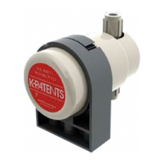
1 Introduction 1 Introduction The inline refractometer sensor PR-33-S (figure 1.1) measures the refractive index n and the temperature of the process medium. The concentration of the process liquid is calculated from these values when the composition of the process medium is known. - Page 6 PR-33-S instruction manual Figure 1.2 Refractometer principle The refractive index n changes with the process solution concentration and temper- ature. For most solutions the refractive index increases when the concentration in- creases. At higher temperatures the refractive index is smaller than at lower tempera- tures.
- Page 7 1 Introduction a. Optical image b. CCD element c. CCD output Figure 1.4 Optical image detection © Copyright K-Patents 2015. All rights reserved.
-
Page 8: Ethernet Connection
PR-33-S instruction manual 2 Ethernet connection The Ethernet connection enables data download from a PR-33 sensor to a computer. Any type of computer (PC, Mac, PDA, mainframe...) with a compatible network con- nection can be configured to view and download data from the sensor. Sensor configu- ration and monitoring can be carried out without special software by using a standard web browser. - Page 9 fiber link may be used to extend the range (see figure 2.4). Fiber Media Media converter converter switch PR-33 Figure 2.4 Using fiber link to connect sensor(s). © Copyright K-Patents 2015. All rights reserved.
-
Page 10: Connection Settings
PR-33-S instruction manual 2.2 Connection settings 2.2.1 IP settings for sensor All sensors are shipped with the factory default IP address of 169.254.23.33. This address belongs to the Zeroconf addresses (as defined in IETF standard RFC 3927) so that it can easily be reached from a stand-alone computer (figure 2.1), usually without changing the network settings of the computer. -
Page 11: Configuring A Network Of Sensors
One possibility is to number the instruments so that they all have 192.168.33.x addresses so that every computer and instrument has a different number x between 1...254. The subnet mask (or netmask) is in this case 255.255.255.0 (see figure 2.6). © Copyright K-Patents 2015. All rights reserved. -
Page 12: Testing The Ethernet Connection
PR-33-S instruction manual IP = 192.168.33.1 IP = 192.168.33.2 IP = 192.168.33.3 IP = 192.168.33.100 netmask = 255.255.255.0 Figure 2.6 A network of PR-33 sensors. Note: There are no settings for subnet mask, default gateway or name servers in PR-33, as these settings are not required. -
Page 13: Troubleshooting The Connection
Note: The factory-default IP address of the sensor is 169.254.23.33. This address should always respond (see section 2.2.1). 2.3.1 Troubleshooting the connection In case you are unable to reach the instrument through the network, please check the following things: © Copyright K-Patents 2015. All rights reserved. -
Page 14: Instrument Homepage
Once there is a functional Ethernet connection between the instrument and the com- puter, the homepage can be opened by typing the instrument’s IP address to the ad- dress bar of a web browser. K-Patents recommends using Firefox 2.0 or newer, but most functionality is available with any modern web browser. - Page 15 5. Use the links in the link bar on the left side of the page to find more extensive information on the instrument. Important: In order for the web pages to function as designed, the JavaScript support has to be enabled in the browser. © Copyright K-Patents 2015. All rights reserved.
-
Page 16: Main Page
PR-33-S instruction manual 2.4.1 Main page Once the instrument homepage is loaded, the most important information is visible on the main page (figure 2.10). This page shows the measurement values, serial number and the tag of the instrument. Figure 2.10 Main page (sensor not in process) Document/Revision No. -
Page 17: Parameters
Note: If you change the IP address of the instrument, you will have to enter the new address to the address bar of the browser, as the sensor will no longer exist in the old address. © Copyright K-Patents 2015. All rights reserved. -
Page 18: Diagnostics
PR-33-S instruction manual 2.4.3 Diagnostics On the diagnostics page (figure 2.12) you may see the diagnostic values produced by the sensor. There is also a link to the optical image. The diagnostic values are updated live, but the optical image is only loaded on request. -
Page 19: Inline Refractometer Sensor
The sensor cover should not be exposed to high temperature radiation. In most cases, draft and natural convection provide sufficient air cooling if the air gets to flow freely around the sensor head. © Copyright K-Patents 2015. All rights reserved. -
Page 20: Pr-33-S Sensor Installation
PR-33-S instruction manual 3.1.2 PR-33-S sensor installation PR-33-S SENSOR INSTALLATION MOUNTING RECOMMENDATIONS SENSOR SUPPORT - VERTICAL FLOW 1/2” thread 1/2” thread SENSOR SUPPORT - HORIZONTAL FLOW FLOW CELL ASSEMBLY/DISASSEMBLY MOUNTING COVER ASSEMBLY Cutout in flow cell aperture to align with temperature sensor http://www.kpatents.com/... -
Page 21: Check List For Pipe Mounting
3 Inline refractometer sensor 3.1.3 Check list for pipe mounting Most K-Patents inline refractometer models are mounted in a pipe. K-Patents recom- mends a minimum flow velocity of 1.5 m/s (5 ft/s). The diameter and form of the pipe and the process temperature all affect the measurement and need to be taken into account. -
Page 22: Mounting Cover
Connect the sensor to a PoE switch. Make sure you connect the sensor to a powered port, some switches have both PoE ports and normal ethernet ports. Then connect your laptop or control system to the switch. You can also use a K-Patents FC-11 Field Communicator. - Page 23 3 Inline refractometer sensor © Copyright K-Patents 2015. All rights reserved.
-
Page 24: Startup And Use
PR-33-S instruction manual 4 Startup and use 4.1 Startup 4.1.1 Initial check Connect the sensor to a PoE enabled network, and check that the instrument powers up properly (see section 2.3). Use a web browser to open the instrument homepage and check that the serial number of the instrument corresponds to that on the instru- ment nameplate. -
Page 25: Configuration And Calibration
Figure 5.1 shows how the damping time affects the measure- ment. Note: The factory setting for damping in PR-33-S is 5 s linear. Avoid overdamping, the signal should not be made insensitive. © Copyright K-Patents 2015. All rights reserved. - Page 26 PR-33-S instruction manual 10 s 20 s Time [s] Exponential damping 15 s 30 s Time [s] Linear damping Figure 5.1 Effect of damping time on measurement Document/Revision No. Rev. 1.4 Effective: May 15, 2015...
-
Page 27: Calibrating The Concentration Measurement
3. The chemical curve: The sensor calculates the concentration value based on n TEMP according to chemical curves derived from available chemical literature and K-Patents expertise. The result is a temperature compensated calculated concen- tration value CALC. 4. Field calibration: Adjustment of the calculated concentration value CALC may be required to compensate for some process conditions or to fit the measurement to... -
Page 28: The Chemical Curve
Table 5.1 The chemical curve parameters A chemical curve is specific to the given process medium, e.g. sucrose or sodium hy- droxide. The set of parameters is given by K-Patents and should not be altered, except in case of changing to another process medium. -
Page 29: Direct Bias Adjustment
The concentration measurement value can also be directly adjusted by changing the field adjustment parameter f00. The value of the bias parameter f00 will be added to the concentration value: NEW CONC OLD CONC © Copyright K-Patents 2015. All rights reserved. -
Page 30: Regular Maintenance
6.1 Preventive replacement of o-ring in EKC265 application The amine based chemical solvent EKC265 is formulated to remove post-etch residue from the wafer. K-Patents Semicon Process Refractometer is widely used to monitor the water content of the solvent. Field studies and experience have shown that the o-ring between the refractometer instrument body and flow cell has limited lifetime in... -
Page 31: Troubleshooting
1. The prism is heavily coated. Remove sensor from line and clean prism manually. 2. There is moisture condensation in the sensor, see Section 7.1.1. 3. The sensor temperature is too high, see Section 7.1.2. © Copyright K-Patents 2015. All rights reserved. -
Page 32: Message Prism Coated
5. There are negative spikes in the optical image. The probable cause is dust or finger- prints on the CCD window. Please contact K-Patents. 6. The CCD card in the sensor is faulty. Please contact K-Patents. 7.2.3 Message PRISM COATED Cause: The optical surface of the prism is coated by the process medium or impurities in the process medium. -
Page 33: Concentration Drift During Normal Operation
7.2.2 NO OPTICAL IMAGE 7.2.6 TEMP MEASUREMENT FAULT 7.1.1 HIGH SENSOR HUMIDITY 7.1.2 HIGH SENSOR TEMP 7.2.5 NO SAMPLE 7.2.3 PRISM COATED 7.2.1 OUTSIDE LIGHT TO PRISM 7.2.4 LOW IMAGE QUALITY NORMAL OPERATION © Copyright K-Patents 2015. All rights reserved. -
Page 34: Ethernet Protocol Specification
For this data acquisition, you’ll need to have suitable software on your computer. You can program a data acquisition program yourself following the specifi- cations below. For examples and ready-made applications, please contact K-Patents. 8.1 Communication protocol The communications protocol is based on UDP/IP to port 50023. It is a client/server protocol, where the sensor is the server and thus only sends information when the client (i.e. -
Page 35: Response Format
Note: All the key identifiers (see Section 8.2 for additional information) are case- insensitive. However, K-Patents recommends that they are written as in this specifi- cation. The server (refractometer) may send the response keys in any order. It will send the mandatory keys (marked with an asterisk in Section 8.2) of the specific request, but it... -
Page 36: Request And Response Errors
PR-33-S instruction manual 8.1.3 Request and response errors When the server (refractometer) detects an error, it responds with an error message (for more information see Section 8.3). An error message can be caused for example by an unknown request or inability to collect data for the mandatory keys of a response. -
Page 37: Refractometer Information
: float, final concentration value CONC : float, internal temperature Tsens : float, process temperature : float, image shadow edge : float, calculated concentration value CALC : float, quality factor : integer, background light BGlight © Copyright K-Patents 2015. All rights reserved. -
Page 38: Error Message Specification
There may also be error-dependent extra keys. Other error codes may be returned. is to be handled as unknown request. Codes with higher numbers refer 0x00000003 to internal errors; contact K-Patents for more information on these. Document/Revision No. Rev. 1.4 Effective: May 15, 2015... -
Page 39: Index
Index ethernet connection 4 angle of refraction 1 external light outside light see outside light BIAS adjustment 25 browser 10 Firefox browser see browser fiber link 5 CALC 23 field calibration 23 CCD element 2 form 39 Chrome service 24 browser see browser flow velocity 15 CONC 24... - Page 40 jacket Parameter page 13 sensor see sensor PoE switch 8 PRISM COATED 28 ping 10 LED value 28 principle of measurement 1 LOW IMAGE QUALITY 28 prism coating 28, 29 Main page 12 moisture see sensor humidity refractive index 1 mounting 15, 17 location 15 pipe diameter 17...
-
Page 41: Ec Declaration Of Conformity
EC declaration of conformity... -
Page 43: Pr-33-S Refractometer Field Calibration Form
PR-33-S refractometer field calibration form Fill in this form and fax it to K-Patents Oy or to your local service representative. For contact information, please see <http://www.kpatents.com/> Sensor serial no: Customer: Address: Fax: Email: Sample description: Solvent (water/other): Laboratory method:... - Page 44 1804 CENTRE POINT CIRCLE, SUITE 106 NAPERVILLE, IL 60653, USA TEL. (630) 955 1545 FAX (630) 955 1585 info@kpatents-usa.com K-PATENTS (SHANGHAI CO.,LTD) ROOM 1509 TOMSON COMMERCIAL BUILDING, NO. 710 PUDONG DISTRICT, SHANGHAI, CHINA TEL+86 21 5087 0597/0598 FAX +86 21 5087 0598...
Need help?
Do you have a question about the PR-33-S and is the answer not in the manual?
Questions and answers