Table of Contents
Advertisement
allen + roth
®
is a registered trademark
of LF, LLC. All Rights Reserved.
Purchase Date
Questions, problems, missing parts? Before returning to your retailer, call our customer
service department at
8 a.m. - 5 p.m., EST, Friday.
PH18730
welcoming • sophisticated • inspiring
1-866-439-9800, 8 a.m. - 6 p.m., EST, Monday - Thursday,
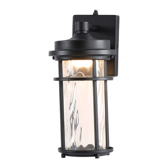
WALL LANTERN
1
800192
APPROVED FOR USE
IN WET LOCATIONS
ITEM #1085704
MODEL #WLL105BK
Français p. 11
Español p. 21
ATTACH YOUR RECEIPT HERE
Advertisement
Table of Contents

Related Manuals for Allen + Roth WLL105BK


Summary of Contents for Allen + Roth WLL105BK
- Page 1 • sophisticated • inspiring 800192 APPROVED FOR USE IN WET LOCATIONS ITEM #1085704 allen + roth ® is a registered trademark of LF, LLC. All Rights Reserved. WALL LANTERN MODEL #WLL105BK Français p. 11 Español p. 21 ATTACH YOUR RECEIPT HERE...
-
Page 2: Table Of Contents
TABLE OF CONTENTS Package Contents ....................... 2 Hardware Contents .......................... 3 Safety Information ....................... 3 Preparation .......................... 5 Assembly Instructions ......................5 Operating Instructions ......................9 Care and Maintenance ......................9 Troubleshooting........................9 Warranty ..........................10 PACKAGE CONTENTS PART DESCRIPTION QUANTITY Fixture Mounting Plate... -
Page 3: Hardware Contents
HARDWARE CONTENTS (shown actual size) Wire Machine Connector Screw Qty. 3 Qty. 2 SAFETY INFORMATION READ AND SAVE THESE INSTRUCTIONS. DANGER • For your protection and safety, carefully read and understand the information provided in this manual completely before attempting to assemble, install or operate this product. Failure to do so could lead to electrical shock, fire or other injuries that could be hazardous or even fatal. - Page 4 SAFETY INFORMATION WARNING • All electrical connections must be in agreement with local codes and ordinances, the National Electric Code (NEC) and ANSI/NFPA 70-1999. Contact your municipal building department to learn about your local codes, permits and/or inspections. Risk of fire - most dwellings built before 1985 have supply wire rated for 140°F.
-
Page 5: Preparation
PREPARATION Before beginning assembly of product, make sure all parts are present. Compare parts with package contents list and hardware contents list. If any part is missing or damaged, do not attempt to assemble the product. Estimated Assembly Time: 30 minutes Tools Required for Assembly (not included): Flathead Screwdriver, Phillips Screwdriver, Wire Strippers, Pliers, Wire Cutters, Safety Glasses, Stepladder, Electrical Tape, Silicone Weather Sealant Helpful Tools (not included): A/C Tester Light, Do-It-Yourself Guide, Soft Cloth, Level... - Page 6 ASSEMBLY INSTRUCTIONS Remove mounting plate (B) and from fixture (A) by removing rubber washers (F) and mounting plate screws (C) from the edges of the fixture (A). Save mounting plate screws (C) and rubber washers (F) for later use. Attach mounting plate (B) to outlet box (not included) using existing washers and outlet box screws or the machine screws (BB).
- Page 7 ASSEMBLY INSTRUCTIONS Unwrap BARE fixture wire from BLACK and WHITE fixture wires. Prepare wires by stripping 3/4 in. of insulation from wire ends using wire strippers (not included). Connect WHITE wire from fixture (A) to WHITE wire from outlet box using existing wire connector or wire connector (AA).
- Page 8 ASSEMBLY INSTRUCTIONS Attach fixture (A) to mounting plate (B) using the rubber washers (F) and mounting plate screws (C) previously removed (Step 3, Page 6). NOTE: Before tightening mounting plate screws (C) completely, use level (not included) to check fixture (A) -- adjust if necessary. Outlet Restore power and test fixture (A).
-
Page 9: Operating Instructions
OPERATING INSTRUCTIONS This fixture can function with either the wall switch or the preassembled dusk-to-dawn sensor (D). To activate the dusk-to-dawn capability, remove the sensor cap (E) from sensor (D). NOTE: For the fixture to work properly, the wall switch to the fixture MUST be turned ON at ALL times. -
Page 10: Warranty
WARRANTY The distributor warrants all of its lighting fixtures against defects in materials and workmanship for five (5) years from the date of purchase. If within this period the product is found to be defective, take a copy of the bill of sale as a proof of purchase and the product in its original carton to the place of purchase.
Need help?
Do you have a question about the WLL105BK and is the answer not in the manual?
Questions and answers