
Subscribe to Our Youtube Channel
Related Manuals for Wacker Neuson LTN6L-V


Summary of Contents for Wacker Neuson LTN6L-V
- Page 1 Operator’s Manual 50 Hz Light Tower LTN6L-V LTN6L-VS Type LTN6L Document 5200004270 Date 1115 Revision Language 5 2 0 0 0 0 4 2 7 0...
- Page 2 Copyright notice © Copyright 2015 by Wacker Neuson Production Americas LLC All rights, including copying and distribution rights, are reserved. This publication may be photocopied by the original purchaser of the machine. Any other type of reproduction is prohibited without express written permission from Wacker Neuson Production Americas LLC.
-
Page 3: Foreword
Expectations This manual provides information and procedures to safely operate and main- tain the above Wacker Neuson model(s). For your own safety and to reduce the information in risk of injury, carefully read, understand, and observe all instructions described this manual in this manual. - Page 4 The information contained in this manual is based on machines manufactured up until the time of publication. Wacker Neuson reserves the right to change any portion of this information without notice. The illustrations, parts, and procedures in this manual refer to Wacker Neuson factory-installed components.
-
Page 5: Table Of Contents
LTN 6L-V Table of Contents Foreword Safety Information Signal Words Used in this Manual ............7 Machine Description and Intended Use ..........8 Safety Guidelines for Operating the Machine ........9 Lamp Safety ..................11 Hydraulic Fluid Safety ................ 11 Service Safety .................. - Page 6 Table of Contents LTN 6L-V Maintenance Preparing for Maintenance ..............41 Periodic Maintenance Schedule ............42 Cleaning the Machine ................43 Inspecting the Machine ...............43 Checking the Engine Oil Level ............44 Flushing the Radiator ................45 Checking the Engine Coolant Level ............47 Checking the Air Cleaning System ............48 Replacing the Air Cleaner ..............49 5.10 Maintaining the Battery ................50...
-
Page 7: Safety Information
LTN 6L-V Safety Information Safety Information Signal Words Used in this Manual This manual contains DANGER, WARNING, CAUTION, NOTICE, and NOTE signal words which must be followed to reduce the possibility of personal injury, damage to the equipment, or improper service. This is the safety alert symbol. -
Page 8: Machine Description And Intended Use
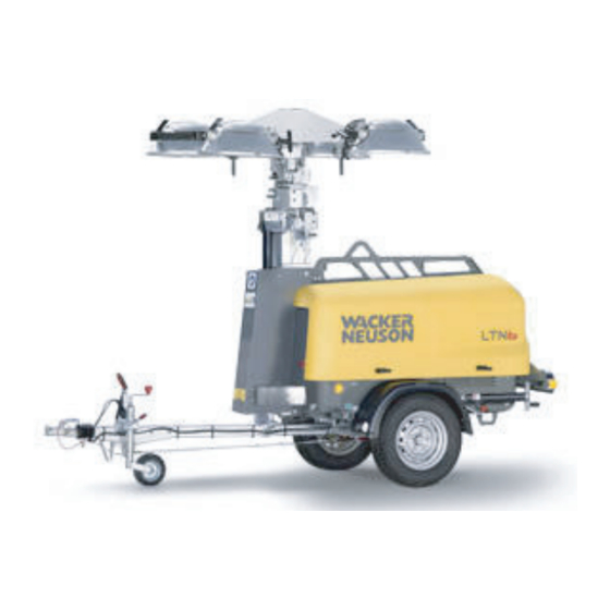
LTN 6L-V Machine Description and Intended Use Machine This machine is a mobile, trailer-mounted light tower. The Wacker Neuson Light description Tower consists of a trailer with a cabinet containing a diesel engine, a fuel tank, a control panel, and an electric alternator. A telescoping tower with four metal halide lights is vertically mounted to the top of the machine. -
Page 9: Safety Guidelines For Operating The Machine
Familiarize yourself with the location and proper use of all controls and safety devices. Contact Wacker Neuson for additional training if necessary. When operating this machine: Do not allow improperly trained people to operate the machine. People operating the machine must be familiar with the potential risks and hazards associated with it. - Page 10 Do not operate the machine if any safety devices or guards are missing or inoperative. Do not modify or defeat the safety devices. Only use accessories or attachments that are approved by Wacker Neuson. Safe When operating this machine: operating Remain aware of the machine’s moving parts.
-
Page 11: Lamp Safety
LTN 6L-V Safety Information Lamp Safety Description The lamps provided with your Light Tower are electric discharge lamps. They are designed for use with metal halide ballasts only, and require time to reach full brightness on initial startup and after a power interruption. These lamps comply with FDA regulation performance standards 21 CFR 1040-30. - Page 12 Machine When servicing or maintaining the machine: modifications Use only accessories/attachments that are approved by Wacker Neuson. When servicing or maintaining the machine: Do not defeat safety devices. Do not modify the machine without the express written approval of Wacker Neuson.
- Page 13 LTN 6L-V Safety Information Cleaning When cleaning and servicing the machine: Keep the machine clean and free of debris such as leaves, paper, cartons, etc. Keep the labels legible. When cleaning the machine: Do not clean the machine while it is running. Never use gasoline or other types of fuels or flammable solvents to clean the machine.
-
Page 14: Operator Safety While Using Internal Combustion Engines
Safety Information LTN 6L-V Operator Safety while Using Internal Combustion Engines WARNING Internal combustion engines present special hazards during operation and fueling. Failure to follow the warnings and safety standards could result in severe injury or death. Read and follow the warning instructions in the engine owner’s manual and the safety guidelines below. -
Page 15: Safety Guidelines For Lifting And Transporting The Machine
LTN 6L-V Safety Information Safety Guidelines for Lifting and Transporting the Machine When lifting the machine: Make sure slings, chains, hooks, ramps, jacks, forklifts, cranes, hoists, and any other type of lifting device used is attached securely and has enough weight- bearing capacity to lift or hold the machine safely. -
Page 16: Labels
Labels LTN 6L-V Labels Label Locations wc_gr009306 wc_si000701gb.fm... - Page 17 LTN 6L-V Labels wc_gr009307 wc_si000701gb.fm...
-
Page 18: Label Meanings
Labels LTN 6L-V Label Meanings WARNING Avoid crushing area. DANGER Contact with overhead electrical power lines will cause serious injury or death. Do not position Light Tower under electrical power lines. Read and understand the supplied Opera- tor’s Manual before operating the machine. Failure to do so increases the risk of injury to yourself and others. - Page 19 LTN 6L-V Labels Fork lift pocket WARNING Roll-over hazard To prevent injury or equipment damage, avoid high speeds and sharp turns when towing. See Operator’s Manual for metal halide lamp information and troubleshooting. BEFORE STARTING THE ENGINE: 1. Check levels of Engine oil Fuel Coolant...
- Page 20 Labels LTN 6L-V WARNING Explosion hazard. Do not use evaporative starting fluids such as ether on this engine. The engine is equipped with a cold starting 5200005891 5200005891 aid. Using evaporative starting fluids can cause an explosion which can cause engine damage, personal injury, or death.
- Page 21 LTN 6L-V Labels WARNING Pressurized contents. Do not open when hot Pinching / cutting hazards. Rotating machin- ery. NOTICE Lifting point 178709 DANGER Using a Light Tower indoors CAN KILL YOU IN MINUTES. Light Tower exhaust contains carbon monoxide. This is a poison you can- not see or smell.
- Page 22 Labels LTN 6L-V Guaranteed sound power level in db(A) Tower and light adjustment switches. The switch on the left controls the up and down movement of the tower. The switch on the right controls the auto- rotation of the tower (optional). DANGER No sparks, flames, or burning objects near machine.
- Page 23 LTN 6L-V Labels WARNING Hot surface 178732 178732 Shutting off the Lights and Lowering the Tower STOP STOP 1. Stop the engine and shut off the lights. 2. Rotate the lights so the light bar is parallel to the machine. To rotate the lights, press the upper or lower half of the switch on the right.
-
Page 24: Lifting The Machine
Lifting the Machine LTN 6L-V Lifting the Machine Overview The machine is equipped with fork lift pockets (a) and a lifting eye (b). wc_gr009316 Requirements Before lifting the machine, make sure that the following requirements have been met. Machine is stopped Tower is completely lowered Lights have been rotated so that they are level with the ground Doors are properly latched... -
Page 25: Operation
1. Make sure all loose packaging materials have been removed from the machine. 2. Check the machine and its components for damage. If there is visible damage, do not operate the machine! Contact your Wacker Neuson dealer immediately for assistance. -
Page 26: Refueling The Machine
Operation LTN 6L-V Refueling the Machine Requirements Machine shut down Engine cool Machine/fuel tank level with the ground Fresh, clean fuel supply Procedure Perform the procedure below to refuel the machine. WARNING Fire hazard. Fuel and its vapors are extremely flammable. Burning fuel can cause severe burns. -
Page 27: Aiming The Lights - Ltn-V
LTN 6L-V Operation Aiming the Lights - LTN-V Overview Each individual light fixture can be aimed up, down, left, or right independent of one another. There are four total light fixtures on each machine. The light bars, which include two light fixtures each, can be tilted 45° in each direction from horizontal. - Page 28 Operation LTN 6L-V Continued from the previous page. Aiming Left or Right 1. Grasp the light fixture and aim it to the light left or right. If necessary, loosen the bracket nut (c) to allow movement of the fixture. NOTICE: Do not loosen the nut (b). Damage to the light fixture may occur. wc_gr010507 2.
- Page 29 LTN 6L-V Operation Continued from the previous page. Aiming the Perform the procedure below to aim the light bars. light bars 1. Loosen the knob (d), grasp the handles (e), and tilt the light bar to the desired angle. 2. Tighten the knob (d) when the light bar is in the desired position. 3.
-
Page 30: Control Panels
Operation LTN 6L-V Control Panels 230V 115V 230VAC g h k l m n wc_gr009945 Ref. Description Ref. Description Floodlight control panel Low oil pressure shutdown Engine control panel High coolant temp. shutdown Tower switch panel Alternator indicator 25A circuit breaker Auxiliary lights (not used) 30A lights circuit breaker Glow plug indicator... -
Page 31: Before Starting
LTN 6L-V Operation Before Starting Before putting the Light Tower into service, review each item on the following checklist. Light Towers often run unattended for long periods of time. Therefore, it is important to make sure that the machine is set up properly to avoid possible operating problems. -
Page 32: Positioning The Machine
Do not operate the machine near flammable vapors, fuels, or combustibles. CO Alarms Because this machine produces carbon monoxide (CO), Wacker Neuson recommends that CO alarms be installed in all structures in close proximity to the machine. CO alarms provide an extra measure of protection against this poison that you cannot see or smell. -
Page 33: Starting The Machine
LTN 6L-V Operation Starting the Machine Pre-start Check the following items before starting the machine. checklist Engine oil, fuel and coolant are filled to the proper levels. Electrical cables in good condition with no cuts or abrasions in the insulation. Circuit breakers (a, b, c) are in their “OFF”... -
Page 34: Operating The Lights
Operation LTN 6L-V 4.10 Operating the Lights Requirements All items in “Before Starting” checklist have been checked Tower is raised to the desired height Engine is running and has warmed up Procedure Perform the procedure below to operate the lights. 1. -
Page 35: Raising The Tower - Ltn 6L-V
LTN 6L-V Operation 4.11 Raising the Tower - LTN 6L-V Overview The tower is raised by the action of a hydraulic cylinder (c). Note: The tower can be raised without running the engine. WARNING Personal injury hazard. Raising or lowering the tower creates situations that if not avoided, will cause death or serious injury from striking, crushing, pinching, electrocution, etc. -
Page 36: Manually Rotating The Mast
Operation LTN 6L-V 4.12 Manually Rotating the Mast Overview The operator can rotate the mast 360° while the tower is lowered. Procedure To rotate the mast, perform the procedure below. 1. Pull out the locking pin (a) on the bottom of the mast. 2. -
Page 37: Lowering The Tower
LTN 6L-V Operation 4.13 Lowering the Tower Overview A low-voltage electrical circuit controls the release of pressure in the hydraulic cylinder (c). When pressure is released, the tower will lower. Notes The engine does not need to be running to lower the tower. The hydraulic circuit includes a pressure release valve that lowers the tower in an emergency situation. -
Page 38: Automatic Shutdown
If an automatic shutdown occurs, the engine will stop. Return the key switch to the after off position to reset the system. automatic See Troubleshooting or contact Wacker Neuson Product Support if automatic shutdown shutdown frequently occurs. 4.15 Stopping the Machine NOTICE: Do not stop the machine without turning off the lights. -
Page 39: Emergency Shutdown Procedure
LTN 6L-V Operation 4.16 Emergency Shutdown Procedure General If a breakdown or accident occurs while the machine is operating, follow the procedures procedure below: 1. Stop the engine. 2. Disconnect tools. 3. Lower the tower. 4. Allow the machine to cool before opening the cabinet. 5. -
Page 40: Receptacle - 50 Hz
Operation LTN 6L-V 4.17 Receptacle - 50 Hz Description This machine is equipped with a convenience receptacle (d) for running accessories and tools from the generator. A circuit breaker (c) protects the receptacle. Power to the receptacle is available any time the engine is running and the circuit breaker is on. -
Page 41: Maintenance
LTN 6L-V Maintenance Maintenance WARNING A poorly maintained machine can malfunction, causing injuries or permanent damage to the machine. Keep the machine in safe operating condition by performing periodic mainte- nance and making repairs as needed. Preparing for Maintenance Do not perform even routine service (oil/filter changes, cleaning, etc.) unless all electrical components are shut down. -
Page 42: Periodic Maintenance Schedule
Maintenance LTN 6L-V Periodic Maintenance Schedule The table below lists basic machine maintenance. Tasks designated with check marks may be performed by the operator. Tasks designated with square bullet points require special training and equipment. Interval* (hours of service) (10) (250) (500) (1000) -
Page 43: Cleaning The Machine
LTN 6L-V Maintenance Cleaning the Machine When As needed Requirements Clean water supply Mild detergent Clean, dry cloths NOTICE: Do not use a pressure washer to clean this machine. Pressurized water can severely damage the generator and sensitive electronic components. Interior Clean the interior of the machine. -
Page 44: Checking The Engine Oil Level
Maintenance LTN 6L-V Checking the Engine Oil Level When Daily before starting the engine Requirements Engine is stopped and cool to the touch Machine is on a level surface Clean, dry cloth Fresh oil WARNING Burn hazard. Engine, engine oil, muffler, and exhaust pipes become extremely hot during operation. -
Page 45: Flushing The Radiator
LTN 6L-V Maintenance Flushing the Radiator When Every 1000 hours or 2 years Requirements Engine is stopped and cool to the touch Plastic sheet Container of suitable size to collect drained coolant Fresh 50/50 coolant/water solution Procedure Perform the procedure below to flush the radiator. WARNING Burn hazard. - Page 46 Maintenance LTN 6L-V Continued from the previous page. 4. Open the radiator drain (b) and let the coolant drain into the container. wc_gr009465 5. Close the radiator drain. 6. Remove the engine block coolant plug and let the remaining coolant drain into the container.
-
Page 47: Checking The Engine Coolant Level
LTN 6L-V Maintenance Checking the Engine Coolant Level When Daily Requirements Machine shut down Engine cool 50/50 coolant/water solution (as needed) NOTICE: Do not use water alone to fill the radiator. Use a long-life ethylene glycol coolant. Procedure Perform the procedure below to check the engine coolant level. WARNING Burn hazard. -
Page 48: Checking The Air Cleaning System
Maintenance LTN 6L-V Checking the Air Cleaning System When Daily Overview The air cleaning system consists of an air cleaner with a pleated element and inlet pipe. Procedure Perform the procedure below to check the air cleaning system. 1. Make sure the cover on the air cleaner (a) is installed and securely latched. wc_gr009364 2. -
Page 49: Replacing The Air Cleaner
LTN 6L-V Maintenance Replacing the Air Cleaner When Replace the air filter element when the air filter restriction indicator on the control panel illuminates. Requirements Machine shut down Clean, dry cloths Replacement filter element (as needed) Background The air cleaner assembly consists of an enclosure containing a pleated filter element. -
Page 50: Maintaining The Battery
Maintenance LTN 6L-V 5.10 Maintaining the Battery Location The battery (a) is located beneath the control panel. wc_gr009366 WARNING Explosion hazard. Batteries can emit explosive hydrogen gas. Keep all sparks and flames away from the battery. Do not short-circuit battery posts. Safety Observe the following safety precautions to prevent serious damage to the precautions... -
Page 51: Changing The Engine Oil
LTN 6L-V Maintenance 5.11 Changing the Engine Oil When Change the oil and oil filter (d) every 250 hours. On new machines, change oil after first 50 hours of operation. Requirements Engine stopped, but still warm. Plastic sheet Container of suitable size to collect drained oil Fresh engine oil (see Technical Data) Procedures Follow the procedure below to change the engine oil. - Page 52 Maintenance LTN 6L-V Continued from the previous page. Follow the procedure below to replace the oil filter (e). 1. Drain the engine oil as described above. 2. Using a filter wrench, remove the installed oil filter (e). 3.Apply a thin coat of oil to the rubber gasket of the replacement oil filter.
-
Page 53: Checking Fan Belt Tension
LTN 6L-V Maintenance 5.12 Checking Fan Belt Tension When Check the fan belt for proper tension and wear every 250 hours. Overview Correct fan belt tension is critical to proper engine operation. An over-tensioned fan belt can damage the belt and bearings. A fan belt that is too loose or worn may slip, resulting in shortened belt life, increased noise, and loss of power to the fan. -
Page 54: Checking Radiator Hoses
Maintenance LTN 6L-V 5.13 Checking Radiator Hoses When Check the condition of the radiator hoses every 250 hours. Overview Dry, cracked radiator hoses or loose clamps can cause a coolant leak. A coolant leak will cause the engine to overheat, possibly leading to permanent damage. Regular inspection of the radiator hoses will help to identify coolant leaks. -
Page 55: Performing Coolant Solution Analysis
LTN 6L-V Maintenance 5.14 Performing Coolant Solution Analysis When Every 500 hours or 12 months, whichever comes first. Overview Engine coolant must be regularly tested to ensure that it remains at an acceptable pH level. Unacceptably low pH levels in coolant create an acidic mixture that will permanently damage the radiator, engine, and engine-related components. -
Page 56: Testing The Cooling System Pressure
Maintenance LTN 6L-V 5.15 Testing the Cooling System Pressure When Test the cooling system pressure every 1200 hours, or 24 months (whichever comes first). Background The cooling system is under pressure while the engine is operating. Internal or external leaks will cause the cooling system to lose pressure. These leaks can be detected by forcing pressurized air into the radiator cap and cooling system while the engine is stopped. - Page 57 Pressure drops, or the rated operating radiator cap must be replaced. Contact your pressure cannot be reached, Wacker Neuson dealer. 5. Attach the pressure tester to the radiator filler neck (d). 6. Pressure test the cooling system at slightly above the rated operating pressure marked on the radiator cap.
-
Page 58: Removing And Replacing Lamps
Maintenance LTN 6L-V 5.16 Removing and Replacing Lamps Prerequisites Engine shut down Light circuit breakers turned OFF Lamps and fixtures cool to the touch Eye and hand protection WARNING Burn hazard. Lamps become extremely hot in use. Allow lamps and fixtures to cool 10–15 minutes before handling. WARNING Personal injury hazard. - Page 59 LTN 6L-V Maintenance Continued from the previous page. Perform the procedures below to remove and install the lamp. Removing the 1. Remove the screws (a) securing the flange rings (b) and remove the flange lamp rings. wc_gr005881 2. Remove the lens (c) with the gasket (d) attached. 3.
-
Page 60: Long-Term Storage
Maintenance LTN 6L-V 5.17 Long-Term Storage Introduction Extended storage of equipment requires preventive maintenance. Performing these steps helps to preserve machine components and ensures the machine will be ready for future use. While not all of these steps necessarily apply to this machine, the basic procedures remain the same. -
Page 61: Machine Disposal / Decommissioning
LTN 6L-V Maintenance 5.18 Machine Disposal / Decommissioning Introduction This machine must be properly decommissioned at the end of its service life. Responsible disposal of recyclable components, such as plastic and metal, ensures that these materials can be reused—conserving landfill space and valuable natural resources. -
Page 62: Engine Maintenance: Kohler (T4F)
Engine Maintenance: Kohler (T4f) Engine Maintenance: Kohler (T4f) The viscosity of the engine oil is an important factor when determining the correct engine oil to use in your machine. Use an engine oil of appropriate viscosity based on the expected outside air temperature. See the table below. WARNING Most used liquids from this machine such as oil, gasoline, grease, etc., contain small amounts of materials that can cause cancer and other health problems if... - Page 63 Engine Maintenance: Kohler (T4f) The engine maintenance schedule(s) in this chapter are reproduced from the engine owner’s manual. For additional information, see the engine owner’s manual. wc_tx003649gb.fm...
- Page 64 Engine Maintenance: Kohler (T4f) wc_tx003649gb.fm...
- Page 65 Engine Maintenance: Kohler (T4f) wc_tx003649gb.fm...
-
Page 66: Troubleshooting
Fuel circuit failure Check fuel lines. No generator output Main circuit breaker open Close main circuit breaker. Voltage regulator malfunction Call Wacker Neuson for service. Low oil pressure Low oil level Fill engine sump with oil. Clogged oil filter Replace oil filter. - Page 67 LTN 6L-V Troubleshooting Problem Cause Remedy Lamp will not light Lamp is too hot Allow lamp to cool 10–15 minutes before restarting. Faulty lamp connection Check that lamp is tight in socket. Check connections inside connection boxes on light fixtures and tower. Plug connection at fixture is loose or Repair or replace the plug connection.
-
Page 68: Technical Data
Technical Data LTN 6L-V Technical Data Engine Engine Power Rating Net power rating per ISO 3046 IFN. Actual power output may vary due to conditions of specific use. Modell LTN 6L-V, LTN 6L-VS Engine Make Kohler Model LDW 1003 Type 3-cylinder, 4-cycle, liquid-cooled diesel Max. -
Page 69: Generator
LTN 6L-V Technical Data Generator Item Number: LTN 6L, LTN 6L-V, LTN 6L-VS Generator Frequency 50 ± 2 Continuous output Output volts Amps 26.1 Excitation type Capacitor / Brushless Power factor Voltage regulation - ± 6.0 no load to full load Speed 1500 Machine... -
Page 70: Radiation Compliance
Technical Data LTN 6L-V LTN 6L-V Model Unit LTN 6L-VS LTN 6L-VS (Custom) Amperage 26.1 Frequency Power factor Lamp type Metal halide Lamp output 1000 NEMA beam spread type Maximum lighting coverage @ 1204 (12,960) 0.5 ft-candles Sound power level at operator's dB(A) location (L Guaranteed sound power level... -
Page 71: Dimensions - Ltn 6L-V
LTN 6L-V Technical Data Dimensions - LTN 6L-V cm (in.) (90.5) (48) (130) wc_gr010809 Dimensions - LTN 6L-VS cm (in.) (98) (48) (125) wc_gr012212 wc_td000529gb.fm... -
Page 72: Schematics
Schematics LTN 6L-V Schematics 50 Hz wc_tx003106gb.fm... - Page 73 LTN 6L-V Schematics Ref. Description Ref. Description Ref. Description Generator Circuit breaker, 250V 16A Capacitors, 30 µF Terminal strip Battery Light bar Main circuit breaker Engine control panel Fuel solenoid (option) Floodlight receptacles Engine Capacitor, 31.5 µF Receptacle, 230V 16A Hour meter Float switch (option) Circuit breaker, 250V 30A...
-
Page 74: Generator Capacitor Excitation Schematic 50 Hz
Schematics LTN 6L-V Generator Capacitor Excitation Schematic 50 Hz Ref. Description Ref. Description Rotor Capacitor Stator Generator/Terminal block Excitation coils Control box-Main circuit breaker wc_tx003106gb.fm... -
Page 75: Hydraulic Schematic - Ltn 6L-V
LTN 6L-V Schematics Hydraulic Schematic - LTN 6L-V 1-RED 1-RED 3-RED 4-RED 3-RED wc_gr010817 Ref. Description Ref. Description Hydraulic pump Alarm Hydraulic valve Mast switch wc_tx003106gb.fm... -
Page 76: Hydraulic Schematic - Ltn 6L-Vs
Schematics LTN 6L-V Hydraulic Schematic - LTN 6L-VS 2-BK 4-RD 2-BK 4-RD 3-RD 3-RD 1-RD 1-RD wc_gr012213 Ref. Description Ref. Description Hydraulic pump Alarm Hydraulic valve Mast switch Wire Colors Black Yellow Orange Green Brown Purple Blue Violet Clear Shield Pink White Gray... - Page 78 Wacker Neuson Production Americas LLC, N92W15000 Anthony Ave., Menomonee Falls, WI. 53051 Tel.: (262) 255-0500 Fax: (262) 255-0550 Tel.: (800) 770-0957 Wacker Neuson Limited - Room 1701–03 & 1717–20, 17/F. Tower 1, Grand Century Place, 193 Prince Edward Road West, Mongkok, Kowloon, Hongkong. Tel: (852) 3605 5360, Fax: (852) 2758 0032...
Need help?
Do you have a question about the LTN6L-V and is the answer not in the manual?
Questions and answers