Table of Contents
Advertisement
Quick Links
Advertisement
Table of Contents

Related Manuals for Wacker Neuson LTN 6L


Summary of Contents for Wacker Neuson LTN 6L
- Page 1 Operator’s Manual Light Tower LTN 6L 60 Hz 0171883en 1110...
- Page 2 This publication may be photocopied by the original purchaser of the machine. Any other type of reproduction is prohibited without express written permission from Wacker Neuson Corporation. Any type of reproduction or distribution not authorized by Wacker Neuson Corporation represents an infringement of valid copyrights. Violators will be prosecuted. Trademarks All trademarks referenced in this manual are the property of their respective owners.
-
Page 3: Table Of Contents
LTN 6L Table of Contents Foreword Safety Information Signal Words Used in this Manual ............9 Machine Description and Intended Use ..........10 Safety Guidelines for Operating the Machine ........11 Operator Safety while Using Internal Combustion Engines ....13 Lamp Safety .................. - Page 4 Table of Contents LTN 6L 4.15 Automatic Shutdown ................47 4.16 Operating Lights ..................48 4.17 Stopping ....................48 4.18 Derating ....................48 4.19 Receptacle ..................49 Factory Installed Options Block Heater ..................50 Battery Blanket ..................51 Oil Pan Heater ..................51 Maintenance Periodic Maintenance Schedule ............52 Installing / Removing Light Fixtures ............53...
- Page 5 LTN 6L Table of Contents Appendix I—Assembly Instructions Introduction ..................68 10 Appendix II—Assembly Safety 10.1 Signal Words Found in this Manual ............ 70 10.2 Lifting Safety ..................71 10.3 Pre-Assembly Checklist ..............71 11 Appendix III—Standard Pallet Assembly 11.1 Installing the Outriggers and Outrigger Jacks ........
- Page 6 Table of Contents LTN 6L 13.11 Installing the Lights ................94 13.12 Connecting the Wiring at the Junction Box .........95 13.13 Routing the Coil Cord ................97 13.14 Wiring the Ballasts and Terminal Strips ..........98 13.15 Conclusion ..................100 14 Appendix VI—CE Racked Assembly 14.1...
-
Page 7: Foreword
Refer to the separate Repair Manual for detailed instructions on servicing and repairing the machine. If you are missing any of these documents, please contact Wacker Neuson Corporation to order a replacement or visit www.wackerneuson.com. When ordering parts or requesting service information, be prepared to provide the machine model number, item number, revision number, and serial number. - Page 8 Serious injury hazards to the operator and persons in the work area Permanent damage to the machine which will not be covered under warranty Contact your Wacker Neuson dealer immediately if you have questions about approved or unapproved parts, attachments, or modifications.
-
Page 9: Safety Information
LTN 6L Safety Information Safety Information Signal Words Used in this Manual This manual contains DANGER, WARNING, CAUTION, NOTICE, and NOTE signal words which must be followed to reduce the possibility of personal injury, damage to the equipment, or improper service. -
Page 10: Machine Description And Intended Use
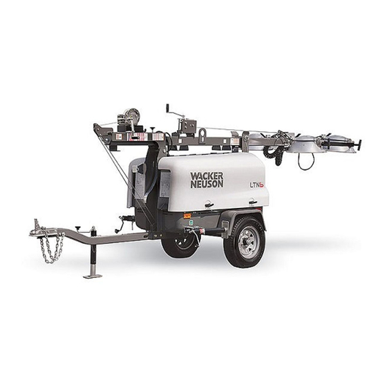
Safety Information LTN 6L Machine Description and Intended Use This machine is a mobile, trailer-mounted light tower. The Wacker Neuson Light Tower consists of a trailer with a cabinet containing a diesel engine, a fuel tank, a control panel, and an electric alternator. A telescoping tower with four metal halide lights is mounted to the top of the cabinet. -
Page 11: Safety Guidelines For Operating The Machine
LTN 6L Safety Information • Heat, noise, exhaust, and carbon monoxide from the engine • Heat from the lights • Ultraviolet radiation from the lights • Fire hazards from improper refueling techniques • Fuel and its fumes • Electric shock and arc flash •... - Page 12 1.3.11 If for any reason any part of the tower hangs up or the winch cable develops slack while raising or lowering the tower, STOP immediately! Contact an authorized Wacker Neuson service representative. 1.3.12 NEVER remove the tower locking pin while the tower is up! 1.3.13 NEVER use the machine if the insulation on the electrical cord is cut or...
-
Page 13: Operator Safety While Using Internal Combustion Engines
LTN 6L Safety Information Operator Safety while Using Internal Combustion Engines WARNING Internal combustion engines present special hazards during operation and fueling. Failure to follow the warnings and safety standards could result in severe injury or death. Read and follow the warning instructions in the engine owner’s manual and the safety guidelines below. -
Page 14: Lamp Safety
Safety Information LTN 6L Lamp Safety Description The lamps provided with your Light Tower are electric discharge lamps. They are designed for use with metal halide ballasts only, and require time to reach full brightness on initial startup and after a power interruption. - Page 15 1.6.7 When replacement parts are required for this machine, use only Wacker Neuson replacement parts or those parts equivalent to the original in all types of specifications, such as physical dimensions, type, strength, and material.
-
Page 16: Labels
Labels LTN 6L Labels Label Locations wc_gr007036 wc_si000381gb.fm... - Page 17 LTN 6L Labels wc_gr007037 wc_si000381gb.fm...
-
Page 18: Label Meanings
Labels LTN 6L Label Meanings Wacker Neuson machines use international pictorial labels where needed. These labels are described below. WARNING Automatic locking pin. A non-secured, falling tower can cause serious injury or death if a person is hit. To secure tower, verify automatic locking pin has been engaged. - Page 19 LTN 6L Labels NOTICE Lifting point. WARNING! Secure tower in transport lock before lifting or towing. A loose swinging tower could cause per- sonal injury or machine damage. DANGER! No sparks, flames, or burning objects near machine. Stop the engine before adding fuel. Use only diesel fuel.
- Page 20 Labels LTN 6L WARNING! Electric shock and arc flash can cause serious injury or death. Electrical storage device within. Contact a qualified electrician for service or to open electrical box. WARNING! Read and understand the supplied Operator’s Manual before operating the machine. Failure to do so increases the risk of injury to yourself and others.
- Page 21 LTN 6L Labels A nameplate listing the model number, item num- ber, revision number, and serial number is attached to each unit. Please record the informa- tion found on this nameplate so it will be available should the nameplate become lost or damaged.
- Page 22 Labels LTN 6L See Operator’s Manual for metal halide lamp information and troubleshooting. Before starting engine Check levels of: Engine oil Fuel Coolant Circuit breakers off Start engine Engine control panel Auto heating Preheat Light out Start, 15 sec. max.
- Page 23 LTN 6L Labels See Operator’s Manual for metal halide lamp information and troubleshooting. Before starting engine Check levels of: Engine oil Fuel Coolant Circuit breakers off Start engine Engine control switch Preheat (30 sec.) Start, 15 sec. max. Circuit breakers on...
- Page 24 Labels LTN 6L Manual Winch System To raise tower: 1. Release transport lock. 2. Tilt tower using winch. 3. Tilt tower until automatic locking pin snaps into place. To increase height of tower: 4. Raise tower using winch. To aim lights: 5.
- Page 25 LTN 6L Labels Manual Winch System To lower tower: 1. Turn off all lights and engine. 2. Rotate tower and tighten knob. 3. Lower tower using winch. To tilt tower for transport: 4. Release and hold spring-loaded pin. 5. Tilt tower using winch.
- Page 26 Labels LTN 6L Power Winch System To raise tower: 1. Release transport lock. 2. Tilt tower using winch. 3. Tilt tower until automatic locking pin snaps into place. To increase height of tower: 4. Raise tower using winch. To aim lights: 5.
- Page 27 LTN 6L Labels Power Winch System To lower tower: 1. Turn off all lights and engine. 2. Rotate tower and tighten knob. 3. Lower tower using winch. To tilt tower for transport: 4. Release and hold spring-loaded pin. 5. Tilt tower using winch.
- Page 28 Labels LTN 6L Guaranteed sound power level in dB(A). Read Operator’s Manual. Use hitch rated from trailer’s “Gross Vehicle Weight Rating”. Securely attach trailer to tow vehicle. Attach safety chains using cross pattern. Attach breakdown chain to vehicle. Check trailer lights.
- Page 29 LTN 6L Labels Transport position of the jack Tie-down point. Low sulfur fuel or ultra low sulfur fuel only. This machine may be covered by one or more patents. U.S.PAT.Nos.: 6012285, 6471476, U.S.PAT.Nos.: 6012285, 6471476, D416858, D454357 OTHER U.S. AND D416858, D454357 OTHER U.S.
-
Page 30: Lifting The Machine
Lifting the Machine LTN 6L Lifting the Machine Procedure See Graphic: wc_gr005415 3.1.1 Check that the tower cradle lock pin (a) is in place and secured with the safety pin. 3.1.2 Ensure that the tower is completely nested inside the transport cradle and the pin (b) is secure. -
Page 31: Operation
LTN 6L Operation Operation Locating Trailer See Graphic: wc_gr005073 4.1.1 For maximum light coverage locate the Light Tower at ground level or in a spot higher than the area being lighted. 4.1.2 Position the trailer on a firm, flat surface clear of overhead wires and obstructions. -
Page 32: Leveling Trailer
Operation LTN 6L Leveling Trailer See Graphic: wc_gr005073, wc_gr005074 The trailer must be leveled and the outriggers extended before raising the tower. The outriggers must remain extended while the tower is up. Failure to level the trailer or extend the outriggers will severely reduce WARNING the stability of the unit and could allow the tower to tip and fall. -
Page 33: Adjusting Lights
LTN 6L Operation Adjusting Lights See Graphic: wc_gr005074 Each light fixture can be aimed up, down, left or right. Position each fixture by loosening toolless light adjusters (g) and aiming the light up or down. DO NOT loosen the inside nut (x). Loosening this nut could cause damage to the light fixture. -
Page 34: Preparing Trailer For Towing Or Lifting
Operation LTN 6L Preparing Trailer for Towing or Lifting See Graphic: wc_gr005073, wc_gr005074 4.4.1 Check that the tower cradle lock pin (j) is in place and secured with the safety pin. 4.4.2 Ensure that the tower is completely nested inside the transport cradle and the pin (t) is secure. -
Page 35: Raising Tower (Manual Winch System)
LTN 6L Operation Raising Tower (Manual Winch System) See Graphic: wc_gr005075 NEVER raise the tower or operate the Light Tower in high winds. NEVER raise the tower while the engine is running. WARNING Do not move the Light Tower while it is operating. - Page 36 Operation LTN 6L 4.5.4 Continue to rotate the winch handle and raise the tower to the vertical position until the vertical tower locking pin (p) locks the tower in place. Be certain the vertical tower locking pin is fully engaged in the locking position before raising the tower.
- Page 37 LTN 6L Operation wc_tx000766gb.fm...
-
Page 38: Lowering Tower (Manual Winch System)
If the tower hangs up, level the trailer. Slightly shake or twist the tower assembly to free the bind. Contact an authorized Wacker Neuson service representative immediately. NEVER lower the tower while the unit is operating. - Page 39 LTN 6L Operation 4.6.4 Pull and hold the tower locking pin (p). Rotate the handle on the tilt winch (o) counterclockwise (“cable out” direction) until the tower spring begins to pivot the tower down. Release the tower locking pin and continue to rotate the handle until the tower is resting in the transport cradle.
-
Page 40: Raising Tower (Power Winch System)
Operation LTN 6L Raising Tower (Power Winch System) See Graphic: wc_gr005076 ALWAYS observe the tower while raising and lowering the tower. NEVER raise the tower or operate the Light Tower in high winds. NEVER raise the tower while the engine is running. - Page 41 LTN 6L Operation 4.7.5 After the tower is in the vertical position, check the operation of the telescoping winch (q). Turn the telescope rotary switch on the control panel to the up position. Do not attempt to raise the tower if the winch is damaged or not operating properly.
-
Page 42: Lowering Tower (Power Winch System)
If the tower hangs up, level the trailer. Slightly shake or twist the tower assembly to free the bind. Contact an authorized Wacker Neuson service representative immediately. NEVER lower the tower while the unit is operating. -
Page 43: Emergency Crank Handle (Power Winch System)
LTN 6L Operation 4.8.4 Pull and hold the tower locking pin (p). Turn and hold the vertical rotary switch (v) on the control panel in the down position until the tower is resting in the transport cradle. Be sure that the secondary locking pin (t) penetrates all sections of the tower. -
Page 44: Control Panels (Manual Winch System)
Operation LTN 6L 4.10 Control Panels (Manual Winch System) Floodlight Control Panel Engine Control Panel Ref. Description Ref. Description 50 Amp circuit breaker High coolant temperature shutdown 30 Amp lights circuit breaker Alternator indicator 20 Amp GFI circuit breaker Auxiliary lights (not used) -
Page 45: Control Panels (120/240, Manual Winch System)
LTN 6L Operation 4.11 Control Panels (120/240, Manual Winch System) Floodlight Control Panel Engine Control Panel WARNING WARNING WARNUNG WARNUNG ADVERTENCIA ADVERTENCIA AVERTISSEMENT AVERTISSEMENT NEUTRAL BONDED TO FRAME NEUTRAL BONDED TO FRAME NULL-LEITER AM RAHMEN NULL-LEITER AM RAHMEN ANGESCHLOSSEN ANGESCHLOSSEN... -
Page 46: Control Panels (Power Winch System)
Operation LTN 6L 4.12 Control Panels (Power Winch System) Floodlight Control Panel Engine Control Panel Ref. Description Ref. Description 50 Amp circuit breaker Alternator indicator 30 Amp lights circuit breaker Auxiliary light (not used) 20 Amp GFI circuit breaker Glow plug indicator... -
Page 47: Starting
LTN 6L Operation 4.13 Starting See Graphic: wc_gr005140, wc_gr006328, wc_gr005141, wc_gr005142 4.13.1 Check engine oil, fuel and coolant levels. Note: If fuel tank was drained or run dry it may be necessary to bleed fuel lines. Refer to engine operator’s manual. -
Page 48: Operating Lights
Operation LTN 6L 4.16 Operating Lights See Graphic: wc_gr005140, wc_gr006328, wc_gr005141, wc_gr005142 Turn on the main circuit breaker (a) first, then turn on each light circuit breaker (b), one at a time. Metal halide floodlights require a warm-up time of 5–15 minutes before they reach full output. -
Page 49: Receptacle
LTN 6L Operation 4.19 Receptacle See Graphic: wc_gr005140, wc_gr006328, wc_gr005141 The control panel is equipped with a convenience receptacle for running accessories and tools from the generator. Power to this receptacle is available any time the engine is running and the circuit breaker is on. -
Page 50: Factory Installed Options
This machine may be equipped with one or more of the following factory-installed options. To verify if any of these options are installed on your machine, contact Wacker Neuson Corporation at 1-800-770-0957. A nameplate listing the Model Number, Item Number, Revision, and Serial Number is attached to each unit. -
Page 51: Battery Blanket
Factory Installed Options Battery Blanket An electrically powered blanket (a) warms the battery while the machine is not in use. The blanket eliminates engine starting difficulties caused by a cold, frozen, or discharged battery. Plug the cord into a 120V power supply. wc_gr007422 Oil Pan Heater Cold, thick engine oil does not flow freely and may cause engine starting... -
Page 52: Maintenance
Maintenance LTN 6L Maintenance Periodic Maintenance Schedule The table below lists basic machine maintenance. Tasks designated with check marks may be performed by the operator. Tasks designated with square bullet points require special training and equipment. Before Every Every Every... -
Page 53: Installing / Removing Light Fixtures
LTN 6L Maintenance Installing / Removing Light Fixtures See Graphic: wc_gr005376 Always turn off light circuit breakers and shut down engine before disconnecting light fixtures or changing lamps. WARNING Remove fixtures by disconnecting electrical cords at the junction box (b). Remove nuts (c) from fixture mounting brackets and remove both fixture and bracket off stud. -
Page 54: Replacing / Removing Lamps
Maintenance LTN 6L Replacing / Removing Lamps Prerequisites • Engine shut down • Light circuit breakers turned OFF • Lamps and fixtures cool to the touch • Eye protection and gloves WARNING Burn hazard. Lamps become extremely hot in use. -
Page 55: Daily Inspection
LTN 6L Maintenance 6.3.2 Remove the lens (c) with the gasket (d) attached. 6.3.3 Remove the hardware securing one side of the lamp stabilizer (e). Once removed, swing the lamp stabilizer to the side and unscrew the lamp (f). Installing the lamp 6.3.4... -
Page 56: Air Cleaner
Maintenance LTN 6L Air Cleaner See Graphic: wc_gr000540 Replace the air filter cartridge when the indicator mounted on the control panel illuminates. 6.5.1 Open air cleaner and remove element. 6.5.2 To clean the filter, lightly tap on a hard surface to eliminate all excess dirt. -
Page 57: Troubleshooting
LTN 6L Maintenance Troubleshooting HIGH VOLTAGE! This unit uses high voltage circuits capable of causing serious injury or death. Only a qualified electrician should troubleshoot or repair electrical problems occurring in this equipment. WARNING Problem / Symptom Reason Remedy Lamp will not light Lamp is too hot. -
Page 58: Technical Data
Technical Data LTN 6L Technical Data Engine Engine Power Rating Net power rating per ISO 3046 IFN. Actual power output may vary due to conditions of specific use. Item Number: LTN 6L Engine Make Lombardini Model LDW1003 Type 3-cylinder, 4-cycle, liquid-cooled diesel Max. -
Page 59: Generator
LTN 6L Technical Data Generator Item Number: LTN 6L LTN 6L 0620297 0620117 0620727 0620550 0620553 0620554 0620561 Generator Frequency 60 ± 2 Continuous output volts/ Output 120, 120/240, 1Ø 1Ø phase Amps Excitation type Capacitor / Brushless Power factor Voltage regulation ±... -
Page 60: Schematics
Schematics LTN 6L Schematics Electrical Schematic wc_tx000936gb.fm... - Page 61 LTN 6L Schematics Ref. Description Ref. Description Generator Battery Terminal strip Engine control panel Main circuit breaker, 50 Amp Engine Floodlights Hour meter Receptacle, 120V Transformers Circuit breaker, 30 Amp Capacitors, 24 mF Circuit breaker, 20 Amp Capacitor, 25 mF...
-
Page 62: Electrical Schematic (120/240)
Schematics LTN 6L Electrical Schematic (120/240) wc_tx000936gb.fm... - Page 63 LTN 6L Schematics Ref. Description Ref. Description Generator Engine control panel Terminal strip Engine Main circuit breaker, 25 Amp Hour meter Floodlights Transformers Receptacle, 120V Capacitors, 24 mF Circuit breaker, 30 Amp Capacitor, 25 mF Circuit breaker, 20 Amp Receptacle, 120/240V Battery –...
-
Page 64: Trailer Wiring
Schematics LTN 6L Trailer Wiring BL BL BL BL YL YL BL BL TONGUE WIRING TONGUE WIRING BL BL YL YL wc_gr005372 Ref. Description Ref. Description Right stop, turn and tail light Side light, red Left stop, turn and tail light... -
Page 65: Engine Wiring - Lombardini
LTN 6L Schematics Engine Wiring - Lombardini Ref. Description Ref. Description Fuel solenoid Air filter restriction indicator (normal open type) Glow plugs Low fuel level switch (not used, normal open type) Starter motor Low oil pressure switch (normal closed type) -
Page 66: Control Panel Wiring
Schematics LTN 6L Control Panel Wiring 7 6 5 wc_gr000658 Ref. Description Ref. Description System fuse, 50 Amp Key switch Glow plug load relay L.E.D. Indicator lamp assembly Auxiliary terminals (rear view) wc_tx000936gb.fm... -
Page 67: Power Winch Schematic
LTN 6L Schematics Power Winch Schematic 5 RD 5 RD 1 BK 1 BK A1 A1 8 BK 8 BK 7 RD 7 RD B2 B2 B1 B1 A2 A2 1 BK 1 BK 2 RD 2 RD 2 RD... -
Page 68: Appendix I-Assembly Instructions
Introduction Scope This Manual contains assembly procedures for racked and palletized versions of Wacker Neuson Narrow-Body Light Towers (LTN). There are separate chapters for each version of the machine. Hardware bags Assembly hardware is packaged in individual bags listed below. (Depending on the model, your Light Tower may or may not include all of these.) - Page 69 Appendix I—Assembly Instructions Illustrations wc_gr006517 wc_tx001218gb.fm...
-
Page 70: Appendix Ii-Assembly Safety
Appendix II—Assembly Safety 10 Appendix II—Assembly Safety 10.1 Signal Words Found in this Manual This is the safety alert symbol. It is used to alert you to potential personal hazards. Obey all safety messages that follow this symbol. DANGER DANGER indicates a hazardous situation which, if not avoided, will result in death or serious injury. -
Page 71: Lifting Safety
Appendix II—Assembly Safety 10.2 Lifting Safety Overview Some of the assembly procedures in this Manual require the machine to be lifted or supported by slings, chains, hooks, ramps, jacks, or other types of mechanical devices. Follow the guidelines below to avoid personal injury or machine damage. -
Page 72: Appendix Iii-Standard Pallet Assembly
Appendix III—Standard Pallet Assembly 11 Appendix III—Standard Pallet Assembly Scope This set of assembly instructions applies to standard machines shipped on a pallet as shown below. wc_gr006467 If your machine does not look like the one shown in the illustration, refer to Machine Identification in the Introduction chapter to identify the appropriate set of assembly instructions. -
Page 73: Installing The Outriggers And Outrigger Jacks
Appendix III—Standard Pallet Assembly 11.1 Installing the Outriggers and Outrigger Jacks Installing the Follow the procedure below to Install the two outriggers. (Use the same procedure for outriggers each side of the Light Tower.) 1. Locate the locking pin (A) at the outrigger socket. wc_gr006520 2. -
Page 74: Installing The Rear Jack
Appendix III—Standard Pallet Assembly 11.2 Installing the Rear Jack Procedure Follow the procedure below to install the rear jack. 1. Locate the 5000 lb.10-inch side crank jack (D). wc_gr006522 2. If necessary, remove the locking pin (D4) from the holes in the jack. 3. -
Page 75: Installing The Tongue Assembly
Appendix III—Standard Pallet Assembly 11.3 Installing the Tongue Assembly Scope Installing the tongue assembly consists of installing the tongue and the tongue jack, and connecting the trailer wiring. Installing the Follow the procedure below to Install the tongue. tongue 1. Insert the tongue (H) into the sleeve at the front of the trailer. wc_gr006523 2. - Page 76 Appendix III—Standard Pallet Assembly Installing the Follow the procedure below to Install the tongue jack. tongue jack 1. Locate the 2000 lb. 10-inch travel jack (“tongue jack”) (J). wc_gr006524 2. If necessary, remove the locking pin (J3) from the holes in the tongue jack. 3.
-
Page 77: Installing The Upper Light Fixtures
Appendix III—Standard Pallet Assembly 11.4 Installing the Upper Light Fixtures Materials Light fixtures (2) needed Hardware bag 6 (tower lights hardware) Procedure Follow the procedure below to install the upper light fixtures. wc_gr007981 Install the two upper light fixtures (CC) on the light tube as follows: 1. -
Page 78: Conclusion
Appendix III—Standard Pallet Assembly 11.5 Conclusion This completes the assembly procedure for your Light Tower. Refer to your Operator’s Manual for instructions on setting up, operating, maintaining, and storing the machine. Notes: wc_tx001214gb.fm... -
Page 79: Appendix Iv-Ce Pallet Assembly
Appendix IV—CE Pallet Assembly 12 Appendix IV—CE Pallet Assembly Overview This set of assembly instructions applies to CE machines shipped on a pallet as shown below. A palletized CE machine is intended to be mounted on a trailer that meets local regulations. This Manual does not include instructions for mounting a palletized CE machine on a trailer. -
Page 80: Installing The Side Jacks
Appendix IV—CE Pallet Assembly 12.1 Installing the Side Jacks Procedure Follow the procedure below to attach the two side jacks. (Use the same procedure for each side jack.) 1. Locate the two 15-inch travel jacks (C). wc_gr006710 2. If necessary, remove the locking pin (C3) from the holes in the jack. 3. -
Page 81: Installing The Rear Jack
Appendix IV—CE Pallet Assembly 12.2 Installing the Rear Jack Procedure Follow the procedure below to install the rear jack. 1. Locate the 5000 lb.10-inch side crank jack (D). wc_gr006711 2. If necessary, remove the locking pin (D4) from the holes in the jack. 3. -
Page 82: Conclusion
Appendix IV—CE Pallet Assembly 12.3 Conclusion This completes the assembly procedure for your Light Tower. Refer to your Operator’s Manual for instructions on setting up, operating, maintaining, and storing the machine. Notes: wc_tx001215gb.fm... -
Page 83: Appendix V-Standard Racked Assembly
Appendix V—Standard Racked Assembly 13 Appendix V—Standard Racked Assembly Overview This set of assembly instructions applies to standard machines shipped on a container rack as shown below. wc_gr006469 If your machine does not look like the one shown in the illustration, refer to Machine Identification in the Introduction chapter to identify the appropriate set of assembly instructions. -
Page 84: Installing The Axle
Appendix V—Standard Racked Assembly Tools and The following tools and materials are needed: materials Basic hand tools (wrenches, screwdrivers, etc.) Torque wrench Hardware bags: 1, 2, 3, 4, 5, 6, 8, and fabricated parts 13.1 Installing the Axle Procedure Follow the procedure below to install the axle: 1. -
Page 85: Installing The Fenders
Appendix V—Standard Racked Assembly 13.2 Installing the Fenders Procedure Follow the procedure below to Install the fenders. 1. Locate the two fenders (W) and hardware bag 2. wc_gr006528 2. Align each fender as shown in the illustration. 3. Install each fender on the Light Tower using (3) M6 x 16 serrated flange screws—but do not tighten the screws until the next step. -
Page 86: Installing The Outriggers And Outrigger Jacks
Appendix V—Standard Racked Assembly 13.4 Installing the Outriggers and Outrigger Jacks Installing the Follow the procedure below to Install the two outriggers. (Use the same procedure outriggers for each side of the Light Tower.) 1. Locate the locking pin (A) at the outrigger socket. wc_gr006520 2. -
Page 87: Installing The Rear Jack
Appendix V—Standard Racked Assembly 13.5 Installing the Rear Jack Procedure Follow the procedure below to install the rear jack. 1. Locate the 5000 lb.10-inch side crank jack (D). wc_gr006522 2. If necessary, remove the locking pin (D4) from the holes in the jack. 3. -
Page 88: Installing The Tongue Assembly
Appendix V—Standard Racked Assembly 13.6 Installing the Tongue Assembly Scope Installing the tongue assembly consists of installing the tongue and the tongue jack, and connecting the trailer wiring. Installing the Follow the procedure below to Install the tongue. tongue 1. Insert the tongue (H) into the sleeve at the front of the trailer. wc_gr006523 2. - Page 89 Appendix V—Standard Racked Assembly Installing the Follow the procedure below to Install the tongue jack. tongue jack 1. Locate the 2000 lb. 10-inch travel jack (“tongue jack”) (J). wc_gr006524 2. If necessary, remove the locking pin (J3) from the holes in the tongue jack. 3.
-
Page 90: Installing The Tower Lock Bracket
Appendix V—Standard Racked Assembly 13.7 Installing the Tower Lock Bracket Procedure Follow the procedure below to Install the tower lock bracket. 1. Locate the following in hardware bag 5: (1) tower lock bracket (M) (3) M8 x 20 hex head mounting screws (N) (3) M8 flat washers (O) (3) M8 lock nuts (P) wc_gr006526... -
Page 91: Installing The Tower Cradle
Appendix V—Standard Racked Assembly 13.8 Installing the Tower Cradle Materials Tower cradle needed Hardware bag 4 (tower cradle hardware) Procedure Follow the procedure below to assemble the tower cradle (Y). wc_gr006530 1. Using (4) M10 x 16 serrated flange screws (Y1), install the tower cradle to the Light Tower upper frame. -
Page 92: Installing The Tower
Appendix V—Standard Racked Assembly 13.9 Installing the Tower Materials Tower assembly needed Hardware bag 8 (tower install assembly) Installing the Follow the procedure below to install the tower. tower wc_gr006531 1. Align the tower assembly (Z) on top of the Light Tower enclosure as shown. 2. -
Page 93: Installing The Tower Pivot Cable
Appendix V—Standard Racked Assembly 13.10 Installing the Tower Pivot Cable Materials Tower pivot cable (AA8) needed Hardware Bag 8 (Tower Install Assembly) Installing the Follow the procedure below to install the tower pivot cable. tower wc_gr006532 1. One end of the tower pivot cable has a loop. Insert the retainer pin (AA5) through the hole in the upper pulley mount (AA9) and pass it through the cable loop. -
Page 94: Installing The Lights
Appendix V—Standard Racked Assembly 13.11 Installing the Lights Materials Light fixtures (4) needed Hardware bag 6 (tower lights hardware) Procedure Follow the procedure below to install the lights. wc_gr006533 1. Install the light mount tube (BB) on the tower using (2) M16 x 90 screws (BB1), (2) B17 flat washers (BB2), and (2) M16 lock nuts (BB3). -
Page 95: Connecting The Wiring At The Junction Box
Appendix V—Standard Racked Assembly 13.12 Connecting the Wiring at the Junction Box Special tools Coil cord (GG) and materials Panduit® crimper CT-100 needed Panduit® crimper CT-1550 Hardware bag 6 Procedure Follow the procedure below to connect the wiring at the junction box. wc_gr006534 Installing the 1. - Page 96 Appendix V—Standard Racked Assembly Connecting 6. Refer to the table below and connect the light fixture wires to the coil cord wires. the wires Use the small connectors and Panduit wire crimper CT-100. Position Light wire Coil cord wire Black White Orange Green...
-
Page 97: Routing The Coil Cord
Appendix V—Standard Racked Assembly 13.13 Routing the Coil Cord Procedure Follow the procedure below to route the coil cord. wc_gr006536 1. At the base of the tower, wrap the coil cord around the tower twice, creating loops of about 25 cm (10 in.) in diameter. 2. -
Page 98: Wiring The Ballasts And Terminal Strips
Appendix V—Standard Racked Assembly 13.14 Wiring the Ballasts and Terminal Strips Procedure Follow the procedure below to wire the ballasts and terminal strips. wc_gr006537 1. Remove the two ballast covers (BC) from the left and right sides of the Light Tower. - Page 99 Appendix V—Standard Racked Assembly “A” “B” wc_gr006538 Terminal strip “A” (right side of machine) Position Wire description A–F Not used Black / yellow from ballasts #1 and #2 Black (#7) from control box Yellows (2) from ballast #1 Yellows (2) from ballast #2 White (#9) from control box Brown and orange from coil cord Terminal strip “B”...
-
Page 100: Conclusion
Appendix V—Standard Racked Assembly 13.15 Conclusion This completes the assembly procedure for your Light Tower. Refer to your Operator’s Manual for instructions on setting up, operating, maintaining, and storing the machine. Notes: wc_tx001216gb.fm... -
Page 101: Appendix Vi-Ce Racked Assembly
LTN Assembly Appendix VI—CE Racked Assembly 14 Appendix VI—CE Racked Assembly Overview This set of assembly instructions applies to CE machines shipped on a container rack as shown below. wc_gr006470 If your machine does not look like the one shown in the illustration, refer to Machine Identification in the Introduction chapter to identify the appropriate set of assembly instructions. - Page 102 Appendix VI—CE Racked Assembly LTN Assembly Tools and The following tools and materials are needed: materials Basic hand tools (wrenches, screwdrivers, etc.) Torque wrench Hardware bags: 1, 2, 3, 4, 5, 6, 8, and fabricated parts wc_tx001217gb.fm...
-
Page 103: Attaching The Outriggers And Outrigger Jacks
LTN Assembly Appendix VI—CE Racked Assembly 14.1 Attaching the Outriggers and Outrigger Jacks Installing the Follow the procedure below to Install the two outriggers. (Use the same procedure outriggers for each side of the Light Tower.) 1. Locate the locking pin (A) at the outrigger socket. wc_gr006520 2. -
Page 104: Attaching The Rear Jack
Appendix VI—CE Racked Assembly LTN Assembly 14.2 Attaching the Rear Jack Procedure Follow the procedure below to install the rear jack. 1. Locate the 5000 lb.10-inch side crank jack (D). wc_gr006522 2. If necessary, remove the locking pin (D4) from the holes in the jack. 3. -
Page 105: Attaching The Tower Lock Bracket
LTN Assembly Appendix VI—CE Racked Assembly 14.3 Attaching the Tower Lock Bracket Procedure Follow the procedure below to Install the tower lock bracket. 1. Locate the following in hardware bag 5: (1) tower lock bracket (M) (3) M8 x 20 hex head mounting screws (N) (3) M8 flat washers (O) (3) M8 lock nuts (P) wc_gr006526... -
Page 106: Installing The Tower
Appendix VI—CE Racked Assembly LTN Assembly wc_gr006530 1. Using (4) M10 x 16 serrated flange screws (Y1), install the tower cradle to the Light Tower upper frame. Torque the screws to 58 Nm (42.8 ft.lbs.) 2. Using (2) M6 x 20 serrated flange screws (Y4), install the radiator access cover (Y2) and radiator cover plate (Y3) to the tower cradle. - Page 107 LTN Assembly Appendix VI—CE Racked Assembly wc_gr006531 1. Align the tower assembly (Z) on top of the Light Tower enclosure as shown. 2. Place the tower assembly over the tower lock pin (Y8) and secure it with the hitch pin. This will help to keep the tower in alignment for the next step. 3.
-
Page 108: Installing The Tower Pivot Cable
Appendix VI—CE Racked Assembly LTN Assembly 14.6 Installing the Tower Pivot Cable Materials Tower pivot cable (AA8) needed Hardware Bag 8 (Tower Install Assembly) Installing the Follow the procedure below to install the tower pivot cable. tower wc_gr006532 1. One end of the tower pivot cable has a loop. Insert the retainer pin (AA5) through the hole in the upper pulley mount (AA9) and pass it through the cable loop. -
Page 109: Attaching The Light Mount Bracket And Light Bar
LTN Assembly Appendix VI—CE Racked Assembly 14.7 Attaching the Light Mount Bracket and Light Bar Materials Light mount bracket (HH) needed Light bar (BB) Hardware Bag 6 (Tower Lights Hardware) Procedure Follow the procedure below to attach the light mount bracket and light bar to the tower. -
Page 110: Attaching The Lights
Appendix VI—CE Racked Assembly LTN Assembly 14.8 Attaching the Lights Materials Light fixtures (4) needed Hardware Bag 6 (Tower Lights Hardware) Procedure Follow the procedure below to attach the lights to the tower. wc_gr006533 Attach the four light fixtures (CC) to the light bar as follows: 1. -
Page 111: Wiring The Junction Box
LTN Assembly Appendix VI—CE Racked Assembly 14.9 Wiring the Junction Box Special tools Coil cord (GG) and materials Panduit® crimper CT-100 needed Panduit® crimper CT-1550 Hardware bag 6 Procedure Follow the procedure below to connect the wiring at the junction box. wc_gr006534 Installing the 1. - Page 112 Appendix VI—CE Racked Assembly LTN Assembly Connecting 6. Refer to the table below and connect the light fixture wires to the coil cord wires. the wires Use the small connectors and Panduit wire crimper CT-100. Position Light wire Coil cord wire Black White Orange...
-
Page 113: Routing The Coil Cord
LTN Assembly Appendix VI—CE Racked Assembly 14.10 Routing the Coil Cord Procedure Follow the procedure below to route the coil cord. wc_gr006536 1. At the base of the tower, wrap the coil cord around the tower twice, creating loops of about 25 cm (10 in.) in diameter. 2. -
Page 114: Wiring The Ballasts And Terminal Strips
Appendix VI—CE Racked Assembly LTN Assembly 14.11 Wiring the Ballasts and Terminal Strips Procedure Follow the procedure below to wire the ballasts and terminal strips. wc_gr006537 1. Remove the two ballast covers (BC) from the left and right sides of the Light Tower. - Page 115 LTN Assembly Appendix VI—CE Racked Assembly “A” “B” wc_gr006538 Terminal strip “A” (right side of machine) Position Wire description A–F Not used Black / yellow from ballasts #1 and #2 Black (#7) from control box Yellows (2) from ballast #1 Yellows (2) from ballast #2 White (#9) from control box Brown and orange from coil cord...
- Page 116 Appendix VI—CE Racked Assembly LTN Assembly Result This completes the assembly procedure for your Light Tower. Refer to your Operator’s Manual for instructions on setting up, operating, maintaining, and storing the machine. wc_tx001217gb.fm...
- Page 118 Fax: +49 - (0)89-3 54 02-390 Wacker Neuson Corporation · N92W15000 Anthony Ave. · Menomonee Falls, WI 53051 · Tel. : (262) 255-0500 · Fax: (262) 255-0550 ·Tel. : (800) 770-0957 Wacker Neuson Limited - Room 1701–03 & 1717–20, 17/F. Tower 1, Grand Century Place, 193 Prince Edward Road West, Mongkok, Kowloon, Hongkong.
Need help?
Do you have a question about the LTN 6L and is the answer not in the manual?
Questions and answers
unit starts for 5 seconds and then shuts down, battery indicator light blinks simultaneously and not resetting.
The Wacker Neuson LTN 6L unit may start for 5 seconds and then shut down with a blinking battery indicator light due to the automatic shutdown system. This system shuts off the fuel supply if the engine does not start properly within 30 seconds after turning the key to "RUN".
Possible causes include:
1. Low Oil Pressure or High Temperature – The auto-shutdown system will stop the engine if oil pressure is too low or the engine temperature is too high.
2. Faulty Battery Connection – A blinking battery indicator may signal a weak or faulty battery connection.
3. Generator Output Issues – If the generator voltage is incorrect, the engine may shut down.
4. Fuel Supply Issues – If the fuel supply is restricted, the engine may not continue running.
To reset, turn the key to the "OFF" position before attempting to restart.
This answer is automatically generated