
Related Manuals for Westinghouse LF 708C


Summary of Contents for Westinghouse LF 708C
- Page 1 WASHING MACHINE SERVICE MANUAL CAUTION READ THIS MANUAL CAREFULLY TO DIAGNOSE TROUBLE CORRECTLY BEFORE OFFERING SERVICE. MODEL : LF 708C LF 711C...
- Page 2 Aug. 2002 PRINTED IN KOREA P/No.:3828ER3013H...
-
Page 3: Table Of Contents
CONTENTS 1. SPECIFICATION..........................3 2. FEATURES & TECHNICAL EXPLANATION ................4 3. PARTS IDENTIFICATION ......................6 4. INSTALLATION ..........................7 5. OPERATION ..........................10 6. WIRING DIAGRAM/PROGRAM CHART ..................12 7. TROUBLESHOOTING.........................13 7-1.BEFORE PERFORMING SERVICE ..................13 7-2.TEST MODE ........................13 7-3.HOW TO KNOW THE WATER LEVEL FREQUENCY............13 7-4.ERROR DISPLAY ........................14 8. -
Page 4: Specification
1. SPECIFICATION ITEM LF 708C / LF 711C POWER SUPPLY 240V~, 50Hz PRODUCT WEIGHT 63kg WASHING 150W ELECTRICITY SPIN (800rpm) 300W CONSUMPTION DRAIN MOTOR WASH HEATER 2000W REVOLUTION WASH 45rpm SPEED SPIN LF 708C 400/600/800 rpm LF 711C 400/600/800/1100 rpm OPERATION WATER PRESSURE 0.3-10kgf/cm... -
Page 5: Features & Technical Explanation
2. FEATURES & TECHNICAL EXPLANATION 2-1.FEATURES ■ Jumbo drum Westinghouse’s jumbo drum can wash about 40% more per load than conventional washing machine. A bigger drum improves the wash performance. ■ Protection against wrinkles With the alternate rotation of the drum, wrinkling in the laundry is minimized. - Page 6 2-2.DETERMINE WASHING TIME BY FUZZY LOGIC To get the best washing performance optimal time is determined by sensing of water temperature, selected washing temperature and laundry amount. water temperature washing time the best selected FUZZY washing washing rinse time temperature LOGIC performance spin rhythm, time...
-
Page 7: Parts Identification
3. PARTS IDENTIFICATION Power plug If the supply cord is damaged, it must be replaced by the manufacturer or its service agents or a similarly qualified Drawer person in order to avoid (For detergent and a hazard. fabric softener) Control panel Drain hose Door Lower cover... -
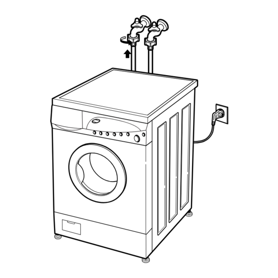
Page 8: Installation
4. INSTALLATION 1⃞ Before servicing ask the customer what the trouble is. 2⃞ Check the adjustment (power supply is 240V, remove the transit bolts..) 3⃞ Check the troubles referring to the troubleshooting. 4⃞ Decide service steps referring to disassembly instructions. 5⃞... - Page 9 ■ HOW TO CONNECT INLET HOSE Check that the rubber washer is inside of the valve connector. Connect the inlet hose firmly to prevent leak. ■ CONNECT DRAIN HOSE · Make sure that the hose is not twisted. · Avoid submerging the end of the hose. ※...
- Page 10 TEST OPERATION Preparation for Press the power button. Press the START/PAUSE washing. button. Connect the power plug to In case of cotton program. the outlet. Connect the inlet hose. Check the water heating. Check automatic reverse Check the water supply. turn.
-
Page 11: Operation
5. OPERATION Rinse hold LED display If you desire to leave fabrics in the machine without spinning after rinse to It displays the remaining time prevent wrinkling, you may select rinse hold by pressing the spin button. (Hour : Minute) to finish. If you want to drain and spin, when Rinse Hold function is proceed, Press In case of abnormal the Start/Pause button to cancel the Rinse Hold function and select spin... - Page 12 Option If you want to elimenate protein stains(milk, blood, chocolate...), you may select Bio by pressing the option button.[You can select Bio when temperature is higher than 60。 C in Cotton and Synthetic.] Rinse + If you wish to rinse more, the Rinse + option will remove any trace of detergents. By selecting Eco, the water temperature is reduced and washing time is lengthened.
-
Page 13: Wiring Diagram/Program Chart
/ PROGRAM CHART 6. WIRING DIAGRAM ❋ Pre Wash : If the laundry is heavily soiled, “Pre Wash” course is effective. Pre Wash is available in Cotton and Synthetic Program. ❋ Eco : By selecting Eco function, the water temperature is reduced and washing time is lengthened. So you can economize in your consumption of energy. -
Page 14: Troubleshooting
Motor rpm (About 45) 2 times Low speed Spin Motor rpm (About 63~67) 3 times Motor rpm (About 79~85) : LF 708C High speed Spin Motor rpm (About 100~106) : LF 711C 4 times Inlet valve for pre-wash operation Water level frequency (25~65) -
Page 15: 7-4.Error Display
7-4.ERROR DISPLAY. If you press the ~Start/Pause₩ button any error except will disappear and the machine will change into pause status. In case of d e , d e , d e , if the error is not resolved within 20 sec. In case of other errors, if the error is not resolved within 4 min. - Page 16 ERROR SYMPTOM CAUSE SENSOR • The electric contact between the connectors ERROR (5-pin, male in the wire harness and 5-pin, female in the hall sensor) is bad or unstable. Reconnect or repair the contact in the connector • The connector (6-pin, male, natural) in the wire harness is not connected to the connector (6-pin, female, natural) of PWB ASSEMBLY (Main) or the electric contact of connectors is bad/unstable.
-
Page 17: Error Diagnosis And Check List
8. ERROR DIAGNOSIS AND CHECK LIST 8-1.DIAGNOSIS AND ANSWER FOR ABNORMAL OPERATION SYMPTOM GUIDE FOR SERVICE CALL NO POWER Is the power plug connected firmly to 240V~ outlet? Power failure? or Breaker opened? Is the outlet controlled by a switch. Visit to check Water inlet trouble displayed? - Page 19 SYMPTOM GUIDE FOR SERVICE CALL ° Suds overflow from the Is low-sudsing detergent for the durm appliance. washing machine used? (In this condition, wash and spin do not operate LOW SUDSING normally) Is the proper amount of detergent used DETERGENT as recommended? Recommend to reduce the amount of detergent.
-
Page 20: Fault Diagnosis And Troubleshooting
8-2.FAULT DIAGNOSIS AND TROUBLESHOOTING CAUTION 1. Be careful of electric shock or disconnecting the parts while troubleshooting. 2. First of all, check the connection of each part terminal with wiring diagram. 3. If you replace the PWB assembly (Main), put in the connectors correctly. NO POWER When measuring the voltage of the outlet, Check the fuse? - Page 21 NO WATER SUPPLY Is the water supply shut-off? Is the tap opened? Open the tap. Check the chamber (Air) When you press both Spin button and Temp. and the tube clogged buttons simultaneously, is the water level frequency below 240? with impurity.
- Page 22 SOFTENER DOES NOT FLOW IN Refer to Is water supplied? ^NO WATER SUPPLY_ Are receptacles correctly connected to the terminals Check the wiring on the of inlet valve? dispenser. Wiring diagram Put it in the correct Is softener put in the correct compartment of compartment.
- Page 23 HEATING WITHOUT WATER When pressing [Spin] and [Temp.] at the same time after draining, is the water level frequency 252 or more? When pressing [Spin], [Temp.] buttons at the same time Replace the sensor while wash, is the water level frequency between (pressure) 240? Checking voltage between two pins as press the...
- Page 24 HEATING CONTINUOUSLY ABOVE THE SETTING WATER TEMPERATURE When disconnect the connector (1) on the PWB assembly (Main) is the resistance of the Natural connectors ~②( Blue/White), Replace the thermistor ③(Blue / White)₩ between 2.5kΩ to 180kΩ (6322FR2046B) (105 ℃ ~0 ℃ )? When checking thermistor on the tub, Push the thermistor is the thermistor loosened above 2mm from...
- Page 25 SPIN TROUBLE Check on the spinning, is the frequency of the Check the sensor water level 248 or more. The frequency can be (Pressure) or hose (Sensor). checked by pressing the Spin and Temp. buttons at If the problem is on the the same time on the program.
-
Page 26: Disassembly Instructions
9. DISASSEMBLY INSTRUCTIONS Be sure to unplug the machine out of the outlet before disassembling and repairing the parts. CONTROL PANEL ① ① Unscrew 2 screws on the back of the top plate. PLATE ASSEMBLY (TOP) ② ② Pull the top plate backward and upward as shown. ①... - Page 27 DISPENSER ASSEMBLY ① ① Disassemble the top plate assembly. ② ② Pull out the drawer to arrow direction. ③ ③ Unscrew 2 screws. DRAWER ① ① The hose clamps and the hose are disassembled. ② ② The ventilation bellows and the water inlet bellows are disassembled on the tub.
- Page 28 INLET VALVE ① ① Disconnect the wiring receptacle. ② ② Unscrew 4 screws from the back. ※When reconnecting the connector VALVE #1 (MAIN) Whited/Black-Black VALVE #2 (PRE) White/Red - Black VALVE #3 (HOT) Blue/White - Black LOWER COVER ■ Open the lower cover plate by using coin and pull out the lower cover in the arrow direction after a screw is unscrewed.
- Page 29 GASKET ASSEMBLY ① ① Take apart the cabinet gasket clamp. ② ② Unscrew 2 screws from the cabinet cover. ③ ③ Open the lower cover cap and unscrew 1 screw inside. ④ ④ Take apart the lower cover. ① ① Unscrew all the screws on the upper and lower sides of the cabinet cover.
- Page 30 PULLEY, MOTOR, DAMPER ① ① Remove the back cover. ② ② Take off the belt turning the pulley. ③ ③ Unscrew the bolt to pull out the pulley. (PULLEY) ① ① Unscrew 2 screws from the bracket. ② ② Push the motor in the arrow direction for disassembling.
- Page 31 PUMP ① ① Remove pump outlet hose. Pump Outlet Hose ② ② Remove tub pump bellows. ③ ③ Remove cap (Remaining Hose.) ④ ④ Disconnect the wiring. Screw ⑤ ⑤ Unscrew 2 screws. ⑥ ⑥ Remove the pump. (Remaining Hose) Tub Pump Bellows HEATER ①...
- Page 32 SWITCH ASSEMBLY, DOOR LOCK ① ① Take apart the cabinet cover clamp and release the gasket. ② ② Unscrew 2 screws holding the door lock. ③ ③ Disconnect the door lock from the wiring connector. WHEN FOREIGN MATERIAL IS STUCK BETWEEN DRUM AND TUB ①...
-
Page 33: Exploded View
10. EXPLODED VIEW 10-1.THE EXPLODED VIEW OF CABINET ASSEMBLY A110 A150 A102 A101 A104 A141 A103 A131 A100 A130 A430 A440 A151 A133 A410 A200 A310 A300 A303 A201 A220 A277 A273 A274 A275 A271 A276 A272 A270... -
Page 34: The Exploded View Of Control Panel & Dispenser Assembly
10-2 THE EXPLODED VIEW OF CONTROL PANEL & DISPENSER ASSEMBLY F170 F160 F300 F432 F220 F430 F120 F310 F110 F210... -
Page 35: The Exploded View Of Drum & Tub Assembly
10-3 THE EXPLODED VIEW OF DRUM & TUB ASSEMBLY K136 K221 K212 K411 K220 K210 K420 K121 K122 K125 K320 K110 K141 K310 K140 K143 K105 K115 K410 K610 K510 K611 K341 K530 K130 K131 F140 K332 K330 K343 K550 K344 K340 K520...
Need help?
Do you have a question about the LF 708C and is the answer not in the manual?
Questions and answers
My machine is labelled on front Mastermind 708 ….not LF 708C is there a user/trouble shooting manual please?
@Lynn Stevens
Yes, there is a service manual available for the Westinghouse Mastermind 708 machine (model LF708C). It contains specifications, features and technical explanations, parts identification, installation instructions, operation details, wiring diagram/program chart, troubleshooting guides, error diagnosis, disassembly instructions, and exploded views.
This answer is automatically generated