Table of Contents
Advertisement
Advertisement
Table of Contents

Summary of Contents for Snapper 447575
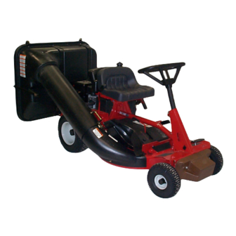
- Page 1 #6-3125 CLAMSHELL GRASS CATCHER KIT For 28” & 33” REAR ENGINE RIDING MOWERS 28” REAR ENGINE RIDER WITH CLAMSHELL BAGGER KIT SHOWN COPYRIGHT © 2000 SNAPPER INC. ALL RIGHTS RESERVED MANUAL No. 7-2887 (I.R. 01/24/00)
-
Page 2: Important Safety Instructions
IMPORTANT SAFETY INSTRUCTIONS All safety instructions and operating instructions in the manuals provided with the Snapper Rear Engine Rider and this Grass Catcher attachment must be followed. Read, understand, and follow ALL instructions and warnings in the Operator’s Manual provided with the machine, with this attachment, and ALL instructions and warnings on the machine, engine and attachment. -
Page 3: Table Of Contents
TABLE OF CONTENTS IMPORTANT SAFETY INSTRUCTIONS ...2 TABLE OF CONTENTS...3 SECTION 1 - ASSEMBLY INSTRUCTIONS... 3-9 Introduction... 3 Right & Left Bumper Bracket Installation ... 4 Hitch Plate & Heat Shield Installation... 5 Hinge Pivot Bolt Installation... 5 Hinge Adjustment – Rear Cover... 6 Front Weight Installation ... -
Page 4: Section 1 - Assembly Instructions
SECTION 1 – ASSEMBLY INSTRUCTIONS INTRODUCTION The 6-3125 Clamshell Grass Catcher kit fits Snapper Rear Engine Riding mowers equipped with 28” and 33” decks. Use the following instructions to assemble the grass catcher components and prepare your machine for collecting grass clippings and leaves. Follow and complete each step carefully. -
Page 5: Hitch Plate & Heat Shield Installation
SECTION 1 – ASSEMBLY INSTRUCTIONS STEP 2 HITCH PLATE AND HEAT SHIELD INSTALLATION A. Attach triangular shaped Hitch Plate to bottom of Front Cover Assembly. Orientation of the holes in the hitch plate is important, observe picture carefully before assembling. Align holes in Hitch Plate and Front Cover Frame. -
Page 6: Hinge Adjustment - Rear Cover
SECTION 1 – ASSEMBLY INSTRUCTIONS STEP 4 HINGE ADJUSTMENT – REAR COVER The holes in the rear Hinge Plate are slotted and adjustment may be required to insure a proper seal between the front and rear Covers. A. Insert hook on the right Rear Cover Assembly into round hole in right Handle Link. -
Page 7: Air Lift Kit, #6-0480 Installation
Front Weight. Series 19, “M” model riders already have the holes drilled but are covered by the SNAPPER decal. Holes can be located by rubbing lightly over decal. If you have a Series 17 rider, use the dimensions on the illustration provided to mark the locations for drilling the two holes. - Page 8 SECTION 1 – ASSEMBLY INSTRUCTIONS HINGE NUT SPRING FIGURE 1.14 C. Hold the adapter in front of the deck. Align the adapter lugs with the lug retainers in the hinge. Push or lightly tap front of adapter towards the rear until tight against deck.
-
Page 9: Grass Tube Installation
SECTION 1 – ASSEMBLY INSTRUCTIONS STEP 8 GRASS TUBE INSTALLATION A. Attach Tube Handle and Handle Base to Tube before installing Tube to catcher. Insert (2) 1/4-20 x 3/4” Carriage bolts through Handle Base and holes in Tube as shown. See Figure 1.18. -
Page 10: Section 2- Operation & Maintenance
SECTION 2– OPERATION & MAINTENANCE INTRODUCTION Follow operation and maintenance instructions in the Operator’s Manual provided with the Snapper Rear Engine Rider. GRASS CATCHER OPERATION A. Select desired cutting height. Choose a setting that will not attempt to cut off too much at once, overloading the machine. -
Page 11: Clamshell Assembly Components
CLAMSHELL ASSEMBLY COMPONENTS... -
Page 12: Clamshell Assembly Components
ITEM PART NO. DESCRIPTION 1-4517 TUBE, Grass 2-8700 DECAL, Read Manual (Not Shown) 1-1870 GRIP 1-6314 WASHER, 11/32 Flat (9) 3-6422 WASHER, 3/16 Flat (30) 5-8615 WELDMENT, Front Cover Brace 7-2873 COVER, Front 7-2874 DEFLECTOR (Not Shown) 7-2950 GASKET, Chute 9-0307 SCREW, #10-24 x 1/2”... - Page 13 Safety Instructions, Installation & Operator’s Manual For #6-3125 CLAMSHELL GRASS CATCHER KIT For 28” & 33” REAR ENGINE RIDING MOWERS COPYRIGHT © 2000 SNAPPER INC. ALL RIGHTS RESERVED MANUAL No. 7-2887 (I.R. 01/24/00)


Need help?
Do you have a question about the 447575 and is the answer not in the manual?
Questions and answers