Advertisement
Advertisement
Table of Contents

Related Manuals for peerless-AV SS560DPB


Summary of Contents for peerless-AV SS560DPB
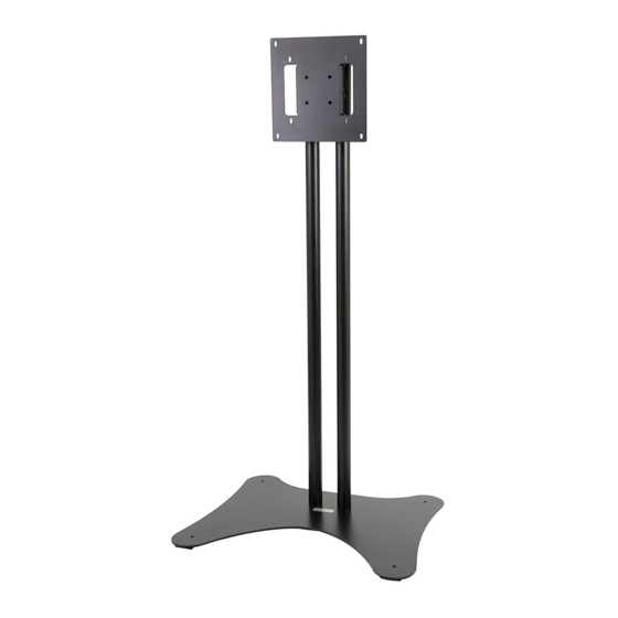
- Page 1 Installation and Assembly: 32" - 65" Flat Panel Display Stand Models: SS560DPB, SS560DPS Max UL Load Capacity: 160 lb (72.5 kg) display 2300 White Oak Circle • Aurora, Il 60502 • (800) 865-2112 • Fax: (800) 359-6500 • www.peerlessmounts.com ISSUED: 09-08-11 SHEET #: 009-9055-5 07-25-12...
-
Page 2: Table Of Contents
NOTE: Read entire instruction sheet before you start installation and assembly. WARNING • Do not begin to install your Peerless product until you have read and understood the instructions and warnings contained in this Installation Sheet. If you have any questions regarding any of the instructions or warnings, for US customers please call Peerless customer care at 1-800-865-2112, for all international customers, please contact your local distributor. -
Page 3: Parts List
Before you begin, make sure all parts shown are included with your product. Parts List SS560DPB SS560DPS Part Number Description Qty. Part Number column bracket 009-1419 009-1419 adapter plate 009-1599 009-1599 column base 009-1415 009-1415 column 009-1418 009-5451 5/16"-18 x 3/8" socket cap screws... -
Page 4: Assembling Cart
Insert columns (D) over column base supports (C) Insert two 1/4-20 x 12mm socket screws (F) into and align cable management holes. Secure columns column bracket (A) using 4mm allen wrench (H), to column base supports using four 5/16" socket leaving 3/16"... -
Page 5: Installing Adapter Plate
Installing Adapter Plate WARNING • Tighten screws so adapter plate is fi rmly attached. Do not tighten with excessive force. Overtightening can cause stress damage to screws, greatly reducing their holding power and possibly causing screw heads to become detached. Tighten to 40 in. • lb (4.5 N.M.) maximum torque. •... - Page 6 Attaching Display using VESA 100, 200 or VESA 300 Mounting Pattern WARNING • If screws don't get three complete turns in the display inserts or if screws bottom out and adapter plate is still not tightly secured, damage may occur to display or product may fail. For Flat Back Display Select the screws from the baffl...
-
Page 7: Mounting Flat Panel Display
Mounting Flat Panel Display Attach adapter plate (B) onto 1/4-20 screws of column bracket (A). Insert two 1/4-20 x 12mm screws (F) into holes indicated below for desired display orientation. Tighten all screws using 4mm allen wrench (H). No Tilt 2°... -
Page 8: Cable Management
Cable Management Run cables through columns (D) using cable management holes. CABLE MANAGEMENT HOLES 8 of 9 ISSUED: 09-08-11 SHEET #: 009-9055-5 07-25-12 © 2011, Peerless Industries, Inc. All rights reserved. All other brand and product names are trademarks or registered trademarks of their respective owners. Peerless Industries, Inc. - Page 9 LIMITED FIVE-YEAR WARRANTY Peerless Industries, Inc. (“Peerless”) warrants to original end-users of Peerless® products will be free from defects in material and workmanship, under normal use, for a period of fi ve years from the date of purchase by the original end-user (but in no case longer than six years after the date of the product’s manufacture). At its option, Peerless will repair or replace, or refund the purchase price of, any product which fails to conform with this warranty.
Need help?
Do you have a question about the SS560DPB and is the answer not in the manual?
Questions and answers