Table of Contents
Advertisement
Quick Links
Micro Laser Distance Sensor for IO-Link [CMOS]
HG-C1000L Series
Thank you very much for purchasing Panasonic products.
Please read this Instruction Manual carefully and thoroughly for the correct and opti-
mum use of this product.
Kindly keep this manual in a convenient place for quick reference.
● This product is for the sensing (determination and measurement) of objects. Do
not use this product to secure safety, such as accident prevention which may af-
fect human life and property.
● Do not stare directly into the laser beam, or through observation optical equip-
ment, such as lenses or etc. as it is dangerous.
1
INTENDED PRODUCTS FOR CE MARKING
● This product complies with the following standards / regulations.
<EU Directive>
EMC Directive
<Standards in US / Canada>
CAN/CSA-C22.2 NO. 60947-5-2-14
2
CONFIRMATION OF PACKED CONTENTS
Sensor
Laser warning label (JIS Standards, GB Standards)
FDA certification label
Instruction Manual (Japanese, English)
General Information for Safety, Compliance, and Instructions (23 languages) 1 pc.
3
SAFE USE OF LASER PRODUCT
● For the purpose of preventing any injury which may occur to the user by the use
of the laser product in advance, the following standards have been established by
the IEC Standards, JIS Standards, GB Standards and FDA Standards.
IEC : IEC 60825-1
-2014
JIS : JIS C 6802
-2014
GB : GB 7247.1
-2012
FDA : PART 1040.10
These standards classifies laser products according to the level of hazard and
provide the safety measures for respective classes.
● WARNING label
In Japanese
In English
In Chinese
<Label position>
● An English warning label is attached to this product. When this product is used in Japan or
China, peel off the English warning label, and attach the Japanese or Chinese warning label.
● W hen exporting this product to the United State of America attach the FDA certifi-
cation label to the cable close to the sensing device.
4
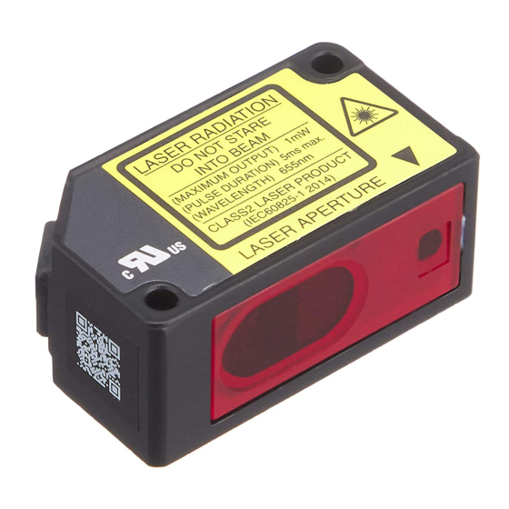
PART DESCRIPTION
Zero set indicator (Yellow)
Teaching indicator (Yellow)
Output operation indicator (Orange)
Laser emission indicator (Green)
TEACH key
Name
Zero set indicator (Yellow)
Lights when zero set function is enabled.
Teaching indicator (Yellow)
Lights when teaching is in process.
Output operation indicator
Lights when output is ON.
(Orange)
Laser emission indicator
Lights when laser beam is ON.
(Green)
<During IO-Link non communication>
PRO indicator (Yellow)
• Lamp OFF when in normal status
• Lights when in PRO mode
INSTRUCTION MANUAL
ME-HGC1000L No.0061-57V
WARNING
1 pc. each language
● F DA certification label
PRO indicator (Yellow)
Digital indicator (Red)
UP key
DOWN key
Function
<During IO-Link communication>
• Flashes when in normal status
• Lights when in PRO mode
5
MOUNTING
Mounting the Main Unit
● When mounting this product,
use M3 screws (prepare sepa-
rately). Use a tightening torque
of 0.5N·m for mounting.
● When mounting this product
using the sensor mounting
bracket (optional), also use a
tightening torque of 0.5N·m.
Mounting the Main Unit
If the fixed ring loosens, the connector will come off, causing this product to generate
a communication error. Before use, be sure to check that the fixed ring is not loose.
● F irmly tighten the fixed ring by rotating it.
Mounting Direction
● Direction to a movable body
<When there are differences in material and color>
• When performing measurements
of moving objects with exces-
sively different materials and
colors, mount the product per the
following directions to minimize
measurement errors.
<Measurement of rotating objects>
1 pc.
• When measuring rotating objects,
1 set
mount the product as follows.
1 pc.
Measurement can be performed
with minimized effect on the ob-
ject caused by up / down deflec-
tion, position deviation and etc.
<When there is a step>
• When there is a step in the mov-
ing object, mount the product as
follows. Measurement can be
performed with minimized effect
from the edges of the steps.
● Measuring of narrow locations and recesses
• When measuring in narrow loca-
tions or inside holes, mount the
product so that optical path from
the light emitting part to light-
receiving part is not interrupted.
● Mounting the sensor to a wall
• Mount the product as follows, so
that the multiple light reflections
on the wall do not emit to the light-
receiving part. When the reflection
factor on a wall is high, it is effec-
tive to use a dull black color.
6
WIRING
● When used as general-purpose sensor
(Brown / 1) +V
(White / 2) DO
(Black / 4) C/Q (Note)
Load
(Blue / 3) 0V
Note: When the product is used as a general-purpose sensor, the IO-Link communication (C/Q) is generated in the
same way as control output (DO).
<Terminal arrangement of M12 connector type>
Terminal No.
1
4
2
3
7
LIST OF FUNCTIONS
Function
Setting on main unit IO-Link communication setting
Teaching input
Limit-teaching
(UP key)
Teaching
Limit-teaching
(DOWN key)
Teaching cancel
Normal sensing mode
Sensing output
Window comparator
setting
mode (1/2/3-point)
Differential mode
Threshold 1_SL
Threshold setting
Threshold 2_SL
Span setting
Differential mode
Threshold setting Index67_2
Peak / Bottom
Setting
hold function
Release
Save in nonvola-
tile memory
Execute
Release of non-
volatile memory
Key Lock Function Setting / Release Index12
Response Speed Setting 10ms / 5ms / 1.5ms Index66
Note: For the IO-Link communication setting, refer to the attached sheet, "Index List."
M3 screws (pre-
pare separately)
● When connected to IO-Link master
(Brown / 1) +V
(White / 2) DO
+
24V DC
±10%
-
(Black / 4) C/Q
Load
(Blue / 3) 0V
This product
Terminal name
1
+V
2
Control output (DO)
3
0V
4
IO-Link communication (C/Q)
Function
Index2
Output operation setting Light-ON / Dark-ON Index61_1
Hysteresis setting Hysteresis value
Index2
Shift setting
Shift amount setting Shift amount
Index2
Timer setting
Index2
Timer period setting Timer period
Display setting
Hold setting
Index61_2
ECO setting
Reset setting
Index60_1
Emission halt
Index60_2
Instability detec-
Index67_1
tion threshold
Instability detec-
Index84
tion delay time
Index2
Operating time
Index2
Number of data
save operations
Index2
Notification flag
setting
Index2
Notification event code -
Mounting hole
dimensions
18mm
Fixed ring
+V
DI
C/Q
0V
IO-Link master
• Recommended
Extension cable with connectors
on both ends
XS5W series
[OMRON Corporation]
Setting on main unit IO-Link communication setting
Index61_3
Mode
Index74_1
Index74_2
Timer mode
Index64_1
Index64_2
Normal / Invert / Offset Index83
ON/OFF
Index85_1
ON/OFF
Index80
Execute
Index2
-
Index70
-
Index160
-
Index162
-
Index163
-
Index164
-
Index168
Index169
Advertisement
Table of Contents

Related Manuals for Panasonic HG-C1000L Series


Summary of Contents for Panasonic HG-C1000L Series
- Page 1 ME-HGC1000L No.0061-57V ● When mounting this product using the sensor mounting Thank you very much for purchasing Panasonic products. bracket (optional), also use a Please read this Instruction Manual carefully and thoroughly for the correct and opti- mum use of this product.
- Page 2 TEACHING 2-point teaching (Window comparator mode) ● This is method to set the threshold range by conducting the 2-point teaching. If settings are configured simultaneously on the main unit side and on the IO-Link ● When performing 2-point teaching (window comparator mode), preset “Window communication side, the settings that are applied last will be enabled. comparator mode 2”...
-
Page 3: Specifications
THRESHOLD VALUE FINE ADJUSTMENT FUNCTION KEY LOCK FUNCTION ● Fine adjustment of the threshold can be performed in the measurement display. ● The key lock function is to prevent acceptance of key operations, so that the con- ● Fine adjustment of the threshold can be performed even after teaching. ditions set in each setting mode are not changed accidentally. - Page 4 Reset setting “ ”: Reset NG, “ ”: Reset OK http://panasonic.net/id/pidsx/global Overseas Sales Division (Head Office) 2431-1 Ushiyama-cho, Kasugai-shi, Aichi, 486-0901, Japan Phone: +81-568-33-7861 FAX: +81-568-33-8591 For sales network, please visit our website. PRINTED IN CHINA © Panasonic Industrial Devices SUNX Co., Ltd. 2018...
Need help?
Do you have a question about the HG-C1000L Series and is the answer not in the manual?
Questions and answers