Table of Contents
Advertisement
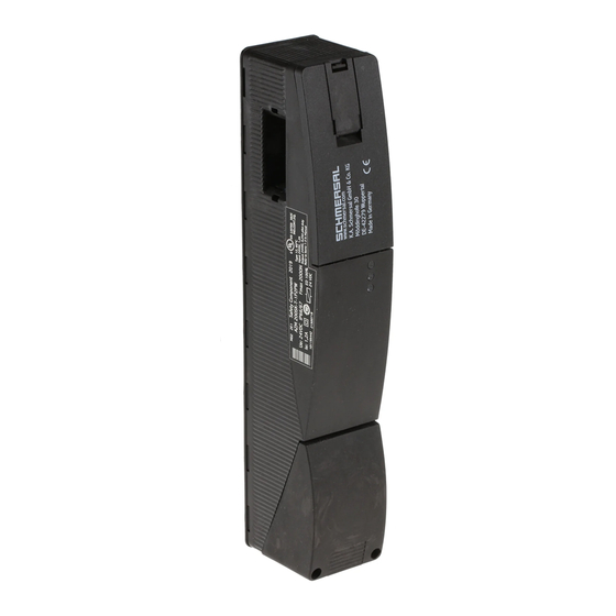
Operating instructions
Solenoid interlock
Operating instructions. . . . . . . . . . . .pages 1 to 10
EN
Original
Content
1
1.1
Function. . . . . . . . . . . . . . . . . . . . . . . . . . . . . . . . . . . . . . . . . . . . .1
1.2
Target group: authorised qualified personnel . . . . . . . . . . . . . . . .1
1.3
Explanation of the symbols used. . . . . . . . . . . . . . . . . . . . . . . . . .1
1.4
Appropriate use . . . . . . . . . . . . . . . . . . . . . . . . . . . . . . . . . . . . . . .1
1.5
General safety instructions . . . . . . . . . . . . . . . . . . . . . . . . . . . . . .1
1.6
Warning about misuse. . . . . . . . . . . . . . . . . . . . . . . . . . . . . . . . . .2
1.7
Exclusion of liability . . . . . . . . . . . . . . . . . . . . . . . . . . . . . . . . . . . .2
2
2.1
Ordering code . . . . . . . . . . . . . . . . . . . . . . . . . . . . . . . . . . . . . . . .2
2.2
Special versions . . . . . . . . . . . . . . . . . . . . . . . . . . . . . . . . . . . . . .2
2.3
Comprehensive quality insurance to 2006/42/EC . . . . . . . . . . . . .2
2.4
Destination and use. . . . . . . . . . . . . . . . . . . . . . . . . . . . . . . . . . . .2
2.5
Technical data . . . . . . . . . . . . . . . . . . . . . . . . . . . . . . . . . . . . . . . .2
2.6
Safety classification. . . . . . . . . . . . . . . . . . . . . . . . . . . . . . . . . . . .3
3
3.1
General mounting instructions. . . . . . . . . . . . . . . . . . . . . . . . . . . .3
3.2
Manual release . . . . . . . . . . . . . . . . . . . . . . . . . . . . . . . . . . . . . . .4
3.3
Dimensions . . . . . . . . . . . . . . . . . . . . . . . . . . . . . . . . . . . . . . . . . .4
4
4.1
General information for electrical connection . . . . . . . . . . . . . . . .4
5
5.1
Magnet control. . . . . . . . . . . . . . . . . . . . . . . . . . . . . . . . . . . . . . . .4
5.2
Mode of operation of the safety outputs . . . . . . . . . . . . . . . . . . . .4
6
6.1
Diagnostic LED's . . . . . . . . . . . . . . . . . . . . . . . . . . . . . . . . . . . . . .5
6.2
Solenoid interlock with conventional diagnostic output . . . . . . . . . 5
6.3
Solenoid interlock with serial diagnostic function . . . . . . . . . . . . .6
7
7.1
Functional testing . . . . . . . . . . . . . . . . . . . . . . . . . . . . . . . . . . . . .7
7.2
Maintenance . . . . . . . . . . . . . . . . . . . . . . . . . . . . . . . . . . . . . . . . .7
8
8.1
Disassembly . . . . . . . . . . . . . . . . . . . . . . . . . . . . . . . . . . . . . . . . .7
8.2
Disposal. . . . . . . . . . . . . . . . . . . . . . . . . . . . . . . . . . . . . . . . . . . . .7
9
9.1
Wiring examples . . . . . . . . . . . . . . . . . . . . . . . . . . . . . . . . . . . . . .8
9.2
Wiring configuration and accessories . . . . . . . . . . . . . . . . . . . . . .9
10
EU Declaration of conformity
1.
About this document
1.1
Function
This operating instructions manual provides all the information you
need for the mounting, set-up and commissioning to ensure the safe
operation and disassembly of the safety switchgear. The operating
instructions must be available in a legible condition and a complete
version in the vicinity of the device.
1.2
Target group: authorised qualified personnel
All operations described in this operating instructions manual must
be carried out by trained specialist personnel, authorised by the plant
operator only.
Please make sure that you have read and understood these operating
instructions and that you know all applicable legislations regarding
occupational safety and accident prevention prior to installation and
putting the component into operation.
The machine builder must carefully select the harmonised standards
to be complied with as well as other technical specifications for the
selection, mounting and integration of the components.
1.3
Explanation of the symbols used
Information, hint, note:
This symbol is used for identifying useful additional information.
Caution: Failure to comply with this warning notice could
lead to failures or malfunctions.
Warning: Failure to comply with this warning notice could
lead to physical injury and/or damage to the machine.
1.4
Appropriate use
The products described in these operating instructions are developed to
execute safety-related functions as part of an entire plant or machine. It
is the responsibility of the manufacturer of a machine or plant to ensure
the correct functionality of the entire machine or plant.
The safety switchgear must be exclusively used in accordance with
the versions listed below or for the applications authorised by the
manufacturer. Detailed information regarding the range of applications
can be found in the chapter "Product description".
1.5
General safety instructions
The user must observe the safety instructions in this operating
instructions manual, the country-specific installation standards as well
as all prevailing safety regulations and accident prevention rules.
Further technical information can be found in the Schmersal
catalogues or in the online catalogue on the Internet:
www.schmersal.net.
The information contained in this operating instructions manual is
provided without liability and is subject to technical modifications.
EN
AZM 200
1
Advertisement
Table of Contents

Subscribe to Our Youtube Channel
Related Manuals for schmersal AZM 200


Summary of Contents for schmersal AZM 200
-
Page 1: Table Of Contents
Diagnostic functions Further technical information can be found in the Schmersal Diagnostic LED's ........5 catalogues or in the online catalogue on the Internet: Solenoid interlock with conventional diagnostic output . -
Page 2: Warning About Misuse
For applications requiring a safe monitoring of the interlocking In case of improper use or manipulation of the safety function, the AZM 200 ... variant must be selected. The AZM switchgear, personal hazards or damages to machinery 200 B ... is a safety switch with additional interlocking function. -
Page 3: Safety Classification
−3 V ... 5 V General mounting instructions Rated operating voltage U 15 V ... 30 V For fitting the AZM 200 solenoid interlock, two mounting holes for M6 High Rated operating current l typically 10 mA at 24 V, screws with washers (washers included in delivery) are provided. -
Page 4: Manual Release
The unlocked safety guard General information for electrical connection can be relocked as long as the actuator is inserted in the AZM 200 solenoid interlock; in that case, the safety outputs are re-enabled. -
Page 5: Diagnostic Functions
Safety guard locked Error Locking time: 150 ... 250 ms, Errors, which no longer guarantee the function of the AZM 200 solenoid Safety guard not locked or fault typically 200 ms interlock (internal error)s cause the safety outputs to be disabled within the risk time. -
Page 6: Solenoid Interlock With Serial Diagnostic Function
Safety outputs Diagnostic outputs Y1, Y2 Power to Power to green red yellow AZM 200 AZM 200 B -1P2P -1P2PW unlock lock Safety guard open 24 V (0 V) 0 V (24 V) Door closed, actuator not inserted 24 V... -
Page 7: Set-Up And Maintenance
Operating instructions Solenoid interlock AZM 200 Table 3: I/O data and diagnostic data Bit n° Request byte Response byte Diagnostic error warning Diagnostic error Bit 0: Magnet in, irrespective of Safety output activated Error output Y1 Error output Y1 power to lock or power to... -
Page 8: Appendix 9.1 Wiring Examples
The series-wiring of multiple AZM 200 solenoid interlocks is realised by wiring in the control cabinet or in on-site junction boxes. In the example, 2 AZM 200 solenoid interlocks (max. 31 components) are wired in series. The diagnostic output ("OUT") and the magnet control ("IN") are separately wired to a conventional PLC for evaluation or control. -
Page 9: Wiring Configuration And Accessories
View of the terminal block for ordering suffix -SK or -CC View of the version with removable terminal blocks 24V 24V 24V 24V AZM 200. - . - 1P2P. AZM 200. - .-SD2P. AZM 200. - . - 1P2P. - . - Page 10 Philip Schmersal Managing Director The currently valid declaration of conformity can be downloaded from the internet at www.schmersal.net. K. A. Schmersal GmbH & Co. KG Möddinghofe 30, D - 42279 Wuppertal Postfach 24 02 63, D - 42232 Wuppertal Phone:...
Need help?
Do you have a question about the AZM 200 and is the answer not in the manual?
Questions and answers