Dell EqualLogic PS4100 Hardware Maintenance Manual
Hide thumbs
Also See for EqualLogic PS4100:
- Hardware manual (50 pages) ,
- Installation and setup manual (41 pages) ,
- Configuration manual (152 pages)
Table of Contents
Advertisement
Advertisement
Table of Contents
Troubleshooting

Subscribe to Our Youtube Channel
Related Manuals for Dell EqualLogic PS4100


Summary of Contents for Dell EqualLogic PS4100
- Page 1 PS4100 Hardware Maintenance Guide Version 1.0...
- Page 2 All trademarks and registered trademarks mentioned herein are the property of their respective owners. Information in this document is subject to change without notice. Reproduction in any manner whatsoever without the written permission of Dell is strictly forbidden. June 2011...
-
Page 3: Table Of Contents
Table of Contents 1 Basic Storage Array Information......................1 Notes, Cautions, and Warnings...........................1 Recommended Tools..............................1 Protecting Hardware ...............................1 Chassis Types................................2 Array Features................................2 The Bezel ................................2 Installing the Bezel..............................2 Front-Panel Features and Indicators ........................3 Back-Panel Features and Indicators ........................4 Shutting Down and Restarting an Array ........................5 2 Maintaining Drives ........................... - Page 4 PS4100 Hardware Maintenance Guide Table of Contents About Control Module Configurations .........................17 Interpreting Control Module LEDs........................18 Identifying Control Module Failures ........................19 Understanding Failover Behavior .........................19 Maintaining Control Module Firmware........................20 Control Module Handling Requirements ......................20 About the Standby On/Off Button ........................21 Replacing a Control Module .............................22 Removing a Control Module..........................22 Installing a Control Module ..........................23...
- Page 5 PS4100 Hardware Maintenance Guide Table of Contents Troubleshooting External Connections........................36 Troubleshooting Power Supply and Cooling Modules .....................36 Troubleshooting Array Cooling Problems........................37 Troubleshooting Control Modules ..........................37 Troubleshooting Hard Drives............................38 Index................................39...
-
Page 7: Basic Storage Array Information
1 Basic Storage Array Information This chapter includes information about the location and basic operation of the replaceable components in a storage array, tools and equipment you will need, protecting hardware from electrostatic discharge, and power on and off operations. Notes, Cautions, and Warnings A NOTE indicates important information that helps you make better use of your system. -
Page 8: Chassis Types
PS4100 Hardware Maintenance Guide Basic Storage Array Information 3. Connect the banana plug to ground, or attach the plug to the alligator clip and connect the clip to a grounded device such as an ESD mat or the metal frame of a grounded piece of equipment. Chassis Types The PS4100 array is available in two different chassis types: •... -
Page 9: Front-Panel Features And Indicators
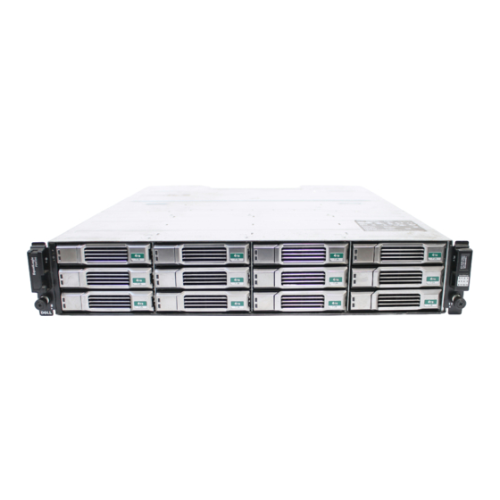
PS4100 Hardware Maintenance Guide Basic Storage Array Information Figure 2 Installing the Bezel Front-Panel Features and Indicators The front of a PS4100, without the bezel, is shown in Figure 3 Figure Table 1 describes the front panel features. Figure 3 Front Panel Features and Indicators (3.5-inch Drives) Figure 4 Front Panel Features and Indicators (2.5-inch Drives) -
Page 10: Back-Panel Features And Indicators
PS4100 Hardware Maintenance Guide Basic Storage Array Information Table 1 Front Panel Feature Descriptions Item Indicator Icon Description Array status The array status LED lights when the array power is on. • Off—No power. • Steady blue—Array status is OK. •... -
Page 11: Shutting Down And Restarting An Array
PS4100 Hardware Maintenance Guide Basic Storage Array Information Table 2 Array Back Panel Features Item Feature Identifier Description Power switches (one None The power switch controls the power supply output to on each power supply) the array. Power supply and PSU0 (left) 700 Watt power supply. - Page 12 Password: Welcome to Group Manager Copyright 2001-2011 Dell, Inc. group1> shutdown If you are using a serial connection to shut down an array, it is safe to turn off power when the “press any key” message appears. (Pressing any key will restart both control modules.) If you are using a network connection, the session will be disconnected before the array is fully shut down.
-
Page 13: Maintaining Drives
Drives are connected to a backplane through drive carriers and are hot-swappable. Drives are supplied in a carrier that is keyed to fit into specific array models, and cannot be installed in other Dell arrays or arrays not from Dell Inc. Identifying Failed Drives A drive failure is indicated by: •... -
Page 14: Array Behavior When A Drive Fails
PS4100 Hardware Maintenance Guide Maintaining Drives Figure 6 LEDs on 3.5-inch Drives Figure 7 LEDs on 2.5-inch Drives Table 4 Drive LED States Description Indicator States Drive activity indicator (ACT LED) Blinking green: Drive is busy Steady green: No drive activity Drive status indicator (PWR LED) Green: Drive OK Amber: Drive failed... -
Page 15: Drive Handling Requirements
PS4100 Hardware Maintenance Guide Maintaining Drives • If a spare drive is not available and the failed drive is in a RAID set that is already degraded, data may be lost and must be recovered from a backup. • If a drive fails, replace it. Do not re-install it in the array. Drive Handling Requirements Handle drives as follows: •... -
Page 16: Removing A 2.5-Inch Drive
PS4100 Hardware Maintenance Guide Maintaining Drives • There is a two-minute delay between the time you insert a drive and the time the drive is automatically configured into a RAID set. This time interval allows multiple drives to be simultaneously configured in an array, which is more efficient than installing a single drive, configuring it, and then repeating the process. -
Page 17: Installing A 2.5-Inch Drive
PS4100 Hardware Maintenance Guide Maintaining Drives Figure 8 Removing a 2.5-Inch Drive Installing a 2.5-inch Drive The 2.5-inch drives are installed vertically, with the drive release latch on the top and the drive label on the bottom. 1. Wear electrostatic protection when handling a drive. See Protecting Hardware on page 1. -
Page 18: Removing A 3.5-Inch Drive
PS4100 Hardware Maintenance Guide Maintaining Drives 4. Push the drive completely into the slot (callout 2). The drive handle will begin to close onto the drive (callout 3). 5. Push in the handle until you hear a click (callout 4). Figure 9 Installing a 2.5-inch Drive Verify that the new drive is operational by examining the LEDs on the front panel, as described in Interpreting Drive LEDs on page... -
Page 19: Installing A 3.5-Inch Drive
PS4100 Hardware Maintenance Guide Maintaining Drives 2. Press the release button (callout 1 in Figure 10). The drive latch opens and the drive emerges partway from the array (callout 2). 3. Pull the drive out by the handle until it is free of the drive bay (callout 3). Figure 10 Removing a 3.5-Inch Drive Installing a 3.5-inch Drive The 3.5-inch drives are installed horizontally, with the drive release latch to the left and the drive label to... -
Page 20: Installing A Drive Blank
PS4100 Hardware Maintenance Guide Maintaining Drives 4. Push the drive completely into the slot (callout 2). The drive handle will begin to close onto the drive (callout 3). 5. Push in the handle until you hear a click (callout 4). Figure 11 Installing a 3.5-inch Drive Verify that the new drive is operational by examining the LEDs on the front panel, as described in Interpreting Drive LEDs on page... -
Page 21: Removing A Drive Blank
PS4100 Hardware Maintenance Guide Maintaining Drives Removing a Drive Blank Warning: To maintain proper system cooling, all empty drive bays must have drive blanks installed. 1. Remove the bezel. See Removing the Bezel on page 2. Press the release tab and slide the drive blank out until it is free of the drive bay. See Figure 12 Figure Figure 12 Removing and Installing a 3.5-Inch Hard-Drive Blank... - Page 22 PS4100 Hardware Maintenance Guide Maintaining Drives...
-
Page 23: Maintaining Control Modules
3 Maintaining Control Modules Different PS Series array models contain different control module types. The combination of chassis type, control module pair, and drives determines the PS Series array model number. The control modules in a PS Series array contain the PS Series firmware which provides the Group Manager GUI, the Command Line Reference, and all the array and storage management functions and features. -
Page 24: Interpreting Control Module Leds
A single control module is a single point of failure. If the control module fails, the entire array (and all the volumes on it) becomes unavailable. Dell strongly recommends buying an array with two control modules, or installing a second control module in a single-controller array. -
Page 25: Identifying Control Module Failures
PS4100 Hardware Maintenance Guide Maintaining Control Modules Table 5 Ethernet and Management Port LED Descriptions LED Location State Description Left No power or not connected to network. Connected to network. Right No power, not transmitting, or not receiving. Transmitting or receiving. Table 6 Control Module Status LED Descriptions LED Name State... -
Page 26: Maintaining Control Module Firmware
PS4100 Hardware Maintenance Guide Maintaining Control Modules Note: The management ports on the control modules do not fail over if one control module fails. Therefore, if you are using a dedicated management network, make sure the management ports on both control modules are connected to the management network. -
Page 27: About The Standby On/Off Button
PS4100 Hardware Maintenance Guide Maintaining Control Modules • Do not leave a control module slot empty. In an array with one control module, always attach a blank face plate to the empty control module slot. • Store control modules properly. Store a control module in its original packaging or in an anti-static bag or place the control module on a surface protected from electrostatic discharge. -
Page 28: Replacing A Control Module
PS4100 Hardware Maintenance Guide Maintaining Control Modules All operations on the member are suspended, there is no I/O activity to or from the member, and the member's firmware is not running. Use the Standby On/Off button only when you need to quickly shut down an array and you may not have access to the GUI or CLI;... -
Page 29: Installing A Control Module
PS4100 Hardware Maintenance Guide Maintaining Control Modules 2. Holding the orange button down, swing the black release latch towards you. This starts to eject the control module from the array. Figure 16 Removing a Control Module 3. Place the control module on a flat surface where it will be protected from electrostatic charge. To avoid damage, do not place anything on top of the control module. -
Page 30: Replacing The Microsd Card
PS4100 Hardware Maintenance Guide Maintaining Control Modules 2. Push down on the orange release tab and swing the black lever out. 3. Slide the control module into the chassis until you feel resistance. Figure 18 Installing a Control Module 4. Rotate the black lever inward, which pushes the control module completely into the slot. The latch on the lever will snap into place. -
Page 31: Removing The Microsd Card
PS4100 Hardware Maintenance Guide Maintaining Control Modules Before replacing a microSD card: • Attach an electrostatic wrist strap, as described in Protecting Hardware on page • See Replacing a Control Module on page 22 for instructions on removing a control module. Removing the MicroSD Card Caution: To reduce the risk of losing or damaging the microSD card, do not remove it until you are ready to install it in the replacement control module. -
Page 32: Inserting The Microsd Card
PS4100 Hardware Maintenance Guide Maintaining Control Modules Inserting the MicroSD Card 1. Align the replacement microSD card so the arrow on the card points towards the housing (Figure 20). 2. Firmly press the card into the housing until it clicks into place. Make sure you cannot pull it out. Figure 20 Inserting the MicroSD Card 3. -
Page 33: Configuring The Management Port
PS4100 Hardware Maintenance Guide Maintaining Control Modules Configuring the Management Port Configuring the 10/100Mbps management port involves hardware steps and software steps. The management port is restricted to group management traffic only; it will not carry iSCSI I/O. Note: This is considered an advanced configuration, available if your environment requires this level of security. - Page 34 PS4100 Hardware Maintenance Guide Maintaining Control Modules...
-
Page 35: Maintaining Power Supply And Cooling Modules
4 Maintaining Power Supply and Cooling Modules The array can support two hot-swappable power supply and cooling modules. The array can operate only temporarily with one module, but both modules must be present for long-term cooling of the array. About AC Power Supplies The PS Series array receives A/C power from two power supply and cooling modules (PSUs). -
Page 36: Removing A Power Supply And Cooling Module
PS4100 Hardware Maintenance Guide Maintaining Power Supply and Cooling Modules Table 7 Power Supply LED Descriptions Item LED Color State Green ON—Normal operation. Power supply is connected to AC power and the power power switch is on. The power supply module is supplying DC power to the array. OFF when any of these is true: •... -
Page 37: Installing A Power Supply And Cooling Module
PS4100 Hardware Maintenance Guide Maintaining Power Supply and Cooling Modules 5. Pull the module from the slot. See Figure Caution: The module is heavy; support it with two hands. Figure 22 Removing a Power Supply and Cooling Module Installing a Power Supply and Cooling Module 1. - Page 38 PS4100 Hardware Maintenance Guide Maintaining Power Supply and Cooling Modules Figure 23 Inserting a Power Supply and Cooling Module 3. Make sure the power switch is in the OFF position. 4. Connect the power cable to the power supply and cooling module and plug the cable into a power outlet. Note: The AC LED lights up when the AC power cable is connected, even if the switches on the power supply are off.
- Page 39 PS4100 Hardware Maintenance Guide Maintaining Power Supply and Cooling Modules Figure 24 : Securing the Power Cable 6. Turn on the switches on the power supply and cooling module.
- Page 40 PS4100 Hardware Maintenance Guide Maintaining Power Supply and Cooling Modules...
-
Page 41: Troubleshooting Your Array
Damage due to servicing that is not authorized by Dell is not covered by your warranty. Read and follow the safety instructions that came with the product. -
Page 42: Obtaining Component Diagnostics
PS4100 Hardware Maintenance Guide Troubleshooting Your Array Obtaining Component Diagnostics You can collect diagnostic information for one or more members of a PS Series group through the Group Manager GUI or the CLI. See the Group Administration guide or the CLI Reference for more information. Troubleshooting Array Startup Failure If your system halts during startup, check if: •... -
Page 43: Troubleshooting Array Cooling Problems
PS4100 Hardware Maintenance Guide Troubleshooting Your Array – Replace the power cable. If the problem is not resolved, or if the power supply’s fault indicator is lit, see Obtaining Technical Support and Customer Service on page Power supply and cooling modules are hot-swappable. The array can operate on a single power supply; however both modules must be installed to ensure proper cooling. -
Page 44: Troubleshooting Hard Drives
PS4100 Hardware Maintenance Guide Troubleshooting Your Array b. Check the link status LED. If the link status LED is not green, proceed to the next step. c. Replace the cables. If the problem is not resolved, see Obtaining Technical Support and Customer Service on page Troubleshooting Hard Drives Check the hard drive indicators before removing the faulty drive from the array. -
Page 45: Index
Index array removing from array ....22 control module restriction ....23 restriction on mixing ....23 control modules ......17 restrictions ........17 cooling ..........29 supported disk type ...... 23 fans ..........29 synchronizing ......20, 22 firmware ........20 types ..........23 LEDs ........7, 18 verifying operational status .. - Page 46 PS4100 Hardware Maintenance Guide Index disks ..........7 network interfaces fans LEDs ..........18 removing ........30 power indicators ....... 3 firmware power supplies identifying version .......20 removing ........30 requirements .........20 PS Series array front panel protecting from discharge ....1 features ...........3 recommended tools ......
- Page 47 PS4100 Hardware Maintenance Guide Index loss of communication ....36 power supply/cooling fan module 36 startup failure .......36...
Need help?
Do you have a question about the EqualLogic PS4100 and is the answer not in the manual?
Questions and answers