Advertisement
Quick Links
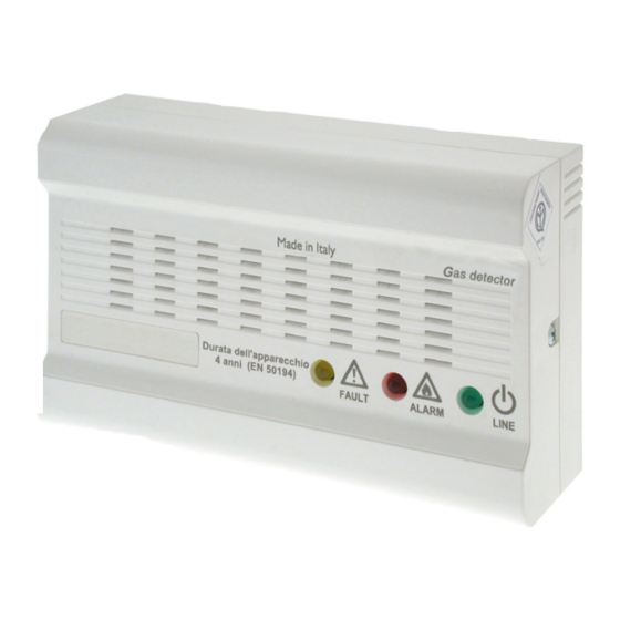
GAS DETECTOR
FOR DOMESTIC INSTALLATION
series GAMMA mod. 652-O/M
series GAMMA mod. 652-O/G
This document refers to gas detected: mod. GAMMA 652-O series marked GECA.
Item
Power supply
652-O/M
230Vac-50/60Hz
652-O/G
230Vac-50/60Hz
GENERAL DESCRIPTION
The detectors are gas detector of methane and LPG gas, that warns
with an optical and acoustic signal, the presence of gas in the
environment.
They are planed to be functioning as detected gas with relay exit.
The detectors are calibrated to detect gas up to 10% of the L.E.L. (Low
Explosion Limit), this threshold can change in base of the
environmental conditions but it will not gets over during the first 4
years working, the 15% LEL, after that period the instrument have to
be put out of order or re-send to manufacturer firm for a complete
substitution of the device.
With that aim, the package is provided with a printed label on which
have to be indicated the maturity of correct working period (4 years
from installing date); this printed label have to be compiled by who
makes the installation.
LUMINOUS AND ACOUSTIC SIGNALISATIONS
The gas detector is provided, on the front panel, by three luminous
signalisations:
-GREEN LED (ON): indicates that the instruments is powered
-YELLOW LED (FAULT): Indicates that the gas sensor is
damaged
-RED LED (ALARM): Indicates that the gas concentration
measured in the air exceeds the alarm threshold
In case of damage, the gas detector is able to signals the malfunction,
illuminating in fixed way the yellow led and activating a sound alarm
with two seconds' of intermittence.
In case of alarm the detector illuminating the red led and after 20
seconds the buzzer emits a sound alarm and the relay activates.
LIGHTING DELAYS
The catalytic sensor presents in the gas detector, needs to be heated
for about one minute to working in a correct way and for that reason
when the detector is lighted on the green led will lighten to indicated
that the sensor is in the heating phase. During this time, all the
detection functions will be inhibited.
Attention: the installation and the out of service of the instrument
English
must be done by skilled personnel only.
The installation of gas and the possible stopping device must be in
according to the national and in force prescriptions law.
The instrument have to be installed:
the gas detector for methane should be fixed at a maximum distance
of 30 cm from the ceiling; the gas detector for LPG should be fixed at
a maximum distance of 30 cm from the floor.
They should be fixed at a distance comprises from 1 meter and 4
meters by the gas device (kitchen, boiler room, etc...)
Made
Made
Made
Made
Made
Possibly in every room in which there is a gas device and, in the
i n i n
i n i n
i n
residences with more that one floor, at least one for each floor.
I t a l y
I t a l y
I t a l y
I t a l y
I t a l y
Detected gas
METHANE
L.P.G.
Avoid installing:
Directly over the sink or the gas device
In little locals where can be utilised alcohol, ammonia, spray bottles
of gas or other substances with flying solvents.
In low ventilated environments
Near to walls or obstacles that can stop the gas flow from the user to
the detector, or near to exhausters or fans that can divert the air flow
In environment in which the temperature can arrive over 40°C or under
–10°C
In environment with a lot of humidity or vapours
By using an screwdriver unscrew on the right hand side the instrument
and uncover it. (Fig.1)
Fig.1
The box cover has to be positioned on the three form point or on the
wall, by using the screws and plugs available. For installing the dowels
drilling the wall with a 5mm drill.
POWER SUPPLY
Attention: the electrical connection has to be done with an under
track cable.
The gas detector have to be powered at 230Vac-50/60Hz by the
terminals 1 and 2 (Fig. 2)
It has to be provided with an device, to be disowned from the detector
and the feeding net with minimun 3mm contact distance in accordance
with as written in the European Standard EN 60335-1.
Fig.2
The detector is provided with an external relay with free tension
contacts, capacity of connection 8A 250Vac / 30Vcc.
INSTALLATION
DETECTOR POSITIONING
30cm
max
1-4m
Methane Detector
INSTALLATION PROCEDURES
ELECTRICAL CONNECTION
1
230Vac - 50/60Hz
CHARACTERISTICS OF THE EXIT-SIGNAL
1-4m
30cm
max
L.P.G. Detector
2
Advertisement

Related Manuals for Geca GAMMA Series


Summary of Contents for Geca GAMMA Series
- Page 1 I t a l y I t a l y I t a l y I t a l y 30cm 1-4m 1-4m This document refers to gas detected: mod. GAMMA 652-O series marked GECA. 30cm Item Power supply Detected gas 652-O/M 230Vac-50/60Hz...
- Page 2 Taking into consideration the fact that the house cooker has a gas ELECTRO-VALVES CONNECTION nozzle of a few tenths of a millimetre and that the gas pressure is of a The gas detector has inside a jumper that permits to select the type of few millibars, the gas flow would allow the delivery of 158,4 litres of electro-valve to connect that can be Normally Opened type (Fig.
- Page 3 1 2 3 4 5 6 7 8 1 2 3 4 5 6 7 1 2 3 4 5 6 7 8 1 2 1 2 Tecnocontrol Srl GECA Srl via Miglioli, n°47 via E.Fermi, n°98 20090 Segrate (MI) Italy 25064 Gussago (BS) Italy Tel.
Need help?
Do you have a question about the GAMMA Series and is the answer not in the manual?
Questions and answers