Advertisement
Quick Links
Advertisement

Related Manuals for jbc FAE1-1A

Summary of Contents for jbc FAE1-1A
- Page 1 www.jbctools.com INSTRUCTION MANUAL Fume Extractor Ref. FAE1-A...
-
Page 2: Packing List
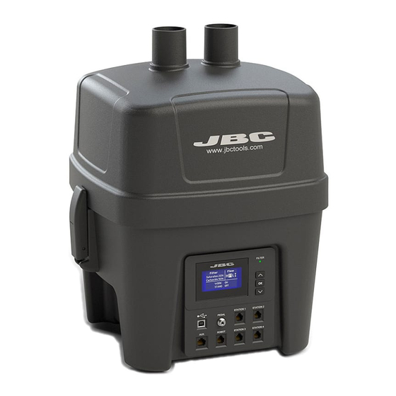
Packing List The following items should be included: Fume Extractor ......... 1 unit RJ12 direct cable ........2 units Ref. FAE1-1A (100V / 120V) Ref. 0019751 FAE1-2A (230V) Power cord ..........1 unit Ref. 0009417 (100V / 120V) 0009401 (230V) H13 Filter &... - Page 3 w w w.jbctools.com Features Aspiration tubes for workbench and tool stands extraction Quick release levers for filter change Process screen Filter saturation indicator: Green: Filter OK Yellow: - ≤ 20% carbon lifetime - ≥ 80% Saturation Red: - End of carbon lifetime - Filter saturated RJ12 station connections...
- Page 4 Accessory for stand aspiration (up to 4 stands) Ref. FAE040 Fume Extractor Flexible Hoses Ø50 To be assembled on Ref. FAE1-1A (100V / 120V) Ref. FAE010 your workbench with the included clamp FAE1-2A (230V) Lenght: 1,5 m (59.05 in) Ref. FAE030...
-
Page 5: Menu Interface
w w w.jbctools.com Turn on the fume extractor Once the fume extractor is turned on, the display shows the following screen and the filter saturation indicator is green. F i l t e r F l o w Saturation Carbon life 100% W O R K OFF S T A N D OFF If the display shows STOP#4, power off the fume extractor, remove the cover, place it back and... - Page 6 Menu Interface Main menu parameters Original PIN: 0105 M a i n m e n u Exit 1 Reset 2 Unit 3 Port 4 Filter set 5 Counters 6 Program version U n i t P o r t F i l t e r s e t Continuous mode Program Ctm - 100%...
- Page 7 w w w.jbctools.com Menu Interface Port menu parameters P o r t Program Ctm - 100% 2 Delay to stop 3 Pedal B a c k D e l a y t o s t o p P e d a l P o r t Work area 5 sec...
- Page 8 Parameters Important: Disconnect any Station or Device from the fume extractor before modifying any parameter. Unit Parameter Description Enable/disable continuous aspiration. When enabled, fume extractor Continuous mode operation is controlled by the main switch of the unit. By default Continuous mode is OFF. Enable/disable the sound of the keypad.
- Page 9 w w w.jbctools.com Port Parameter Description It sets the fume extractor aspiration flow. You can select between a Preset and Custom aspiration program. H (High), M (Medium) or L (Low) are the three Preset available options. Use Up and Down keys to switch between them while being on the main Program screen.
- Page 10 Filter set Parameter Description It shows remaining activated carbon lifetime expressed in %. It is also Carbon life displayed on the main screen. When 0% is reached the system will show pop-up message STOP#1 to replace the filter. It shows saturation status of HEPA + carbon filter set, expressed in %. It is Saturation also displayed on the main screen.
- Page 11 RJ12 station connections Allows connecting JBC Soldering Stations featuring a Robot port to the fume extractor in order to automatically activate the extraction when the tools are in use. (See configuration steps on the soldering station in page 12).
- Page 12 Connection to Soldering Stations featuring ROBOT port Connect up to 4 stations directly to a fume extractor through the Soldering Station Robot port. Every tool connected to a station can control the aspiration system, but previously it has to be assigned to the fume extractor through the Peripherals menu of the station.
- Page 13 QSC makes a bridge function between JBC stations and fume extractors allowing the connection of as many JBC stations as desired to the fume extractor through USB-B connection (USB A-B cables required). QSC includes an easy to use interface to configure which tool will activate the aspiration system when it leaves the stand.
- Page 14 Update the equipment software Fume extractor can be updated by means of JBC Updater software. If you want to update the equipment be aware there is not a station connected to RJ12 connectors. If a station is connected yo RJ12 connector the update process will not start.
-
Page 15: Filter Replacement
w w w.jbctools.com Filter replacement - The unit notifies through both the display and the LED when filters need maintenance. - To replace the filters remove the cover by opening the quick release levers of the casing. - If once the pre-filter has been changed the saturation indicator remains in red, it means that the H13 filter is already saturated and must be replaced too. - Page 16 Filter replacement Connect the filter tube to The filter has a given position. the quick coupling placed Make sure the filter ribs mate on the metal sheet with the corresponding slots. Quick Release Levers Adjustment - Turn clockwise to loosen and counterclockwise to tighten, in order to adjust the filter airtightness. Read safety guidelines to do the equipment maintenance securely.
- Page 17 w w w.jbctools.com Safety Follow safety guidelines to prevent electric shock, injury, fire or explosion. - The equipment is only designed to filtrate the fumes generated by soldering. - Do not use the units for the filtration of combustible, explosive or corrosive gasses. Incorrect use may cause fire.
- Page 18 Notes...
- Page 19 w w w.jbctools.com...
-
Page 20: Specifications
Specifications FAE1-1A 100V 50/60Hz. Input power: 95W Fuse 2A 120V 50/60Hz. Input power: 110W Fuse 2A FAE1-2A 230V 50/60Hz. Input power: 110W Fuse 1.25A - Weight: 10.5 kg (23.2 lb) - Dimensions: 382 x 344 x 476 mm (15 x 13.5 x 18.7 in)