Sign In
Upload
Download
Table of Contents
Contents
Add to my manuals
Delete from my manuals
Share
URL of this page:
HTML Link:
Bookmark this page
Add
Manual will be automatically added to "My Manuals"
Print this page
×
Bookmark added
×
Added to my manuals
Manuals
Brands
Electro-Voice Manuals
Speaker System
X-Line series
Rigging manual
Electro-Voice X-Line series Rigging Manual
Hide thumbs
1
Table Of Contents
2
3
4
5
6
7
8
9
10
11
12
13
14
15
16
17
18
19
20
21
22
23
24
25
26
27
28
29
30
31
32
33
34
35
36
37
38
39
40
41
42
43
44
page
of
44
Go
/
44
Contents
Table of Contents
Bookmarks
Table of Contents
Table of Contents
Rigging-Safety Warning
Introduction
1 Line Rigging System
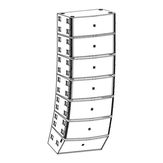
Overview of the X-Line Flying System
Enclosure Rigging Hardware Details
Rear Rigging Hinge Details
Front Rigging Strap Details
Xvbp Pull-Up Bar Details
ATM X-Line Grid Details
RS-1B Double-Stud Rigging Fitting
2 Line Rigging and Flying Techniques
Array Considerations
Adjusting the Vertical Angles of the Enclosures
Deciding Whether to Use an Xvhg or Xvhl at the Grid
Rigging an Array with Boxes Using X-Line Dollies
Pull-Up Techniques
3 Rigging-Strength Ratings, Safety Factors, and Special Safety Considerations
Working-Load Limit (WLL) and Safety Factors
Structural Rating Overview
Simplified Structural-Rating Guidelines
Complex Structural-Rating Analysis
Wind Loading
Electro-Voice Structural-Analysis Procedures
4 Rigging Inspection and Precautions
References
Notes
Advertisement
Quick Links
1
Table of Contents
2
Overview of the X-Line Flying System
3
Electro-Voice Structural-Analysis Procedures
Download this manual
X-Line Rigging Manual
ELECTRO-VOICE
TM
®
X-Line
Rigging Manual
Table of
Contents
Previous
Page
Next
Page
1
2
3
4
5
Advertisement
Table of Contents
Need help?
Do you have a question about the X-Line series and is the answer not in the manual?
Ask a question
Questions and answers
Related Manuals for Electro-Voice X-Line series
Speaker System Electro-Voice XLC Rigging Manual
Electro-voice xlc rigging manual (33 pages)
Speaker System Electro-Voice X-Line Very Compact (XLVC) Rigging Manual
Electro-voice loudspeaker systems rigging manual (56 pages)
Speaker System Electro-Voice ELECTRO-VOICE X-Line TM Rigging Manual
Telex electro-voice x-line tm rigging manual (44 pages)
Speaker System Electro-Voice X-Line XsubF Brochure
X-line series linear array system (2 pages)
Speaker System Electro-Voice X-Line Xvls Brochure
Line arrays (13 pages)
Speaker System Electro-Voice X-Line Very Compact Rigging Manual
Loudspeaker system (32 pages)
Speaker System Electro-Voice Xlvc Series XLD-281 Technical Specifications
3-way, high-output, very compact line-array element (2 pages)
Speaker System Electro-Voice Xlvc Series XLD-281 Brochure & Specs
Line-array systems (16 pages)
Speaker System Electro-Voice Xlvc Series XLE-181 Technical Specifications
2-way, high-output, very compact line-array element (2 pages)
Speaker System Electro-Voice X-LINE ADVANCE Series Installation Manual
(94 pages)
Speaker System Electro-Voice Precision P2000 System Application Manual
Electrovoice precision p2000: reference guide (24 pages)
Speaker System ELECTRO-VOICE Xi-A Series Manual
Xi-a series loudspeaker system flying manual (20 pages)
Speaker System Electro-Voice Xi-1152/94 Quick Start Manual
X-array install two-way, full-range,sound-reinforcement system (8 pages)
Speaker System Electro-Voice X-Array Install Xi-1122-85 Manual
Two-way, full-range, sound-reinforcement system (9 pages)
Speaker System Electro-Voice XJR User Manual
2.1 multimedia speaker system (8 pages)
Speaker System Electro-Voice X-Array Install Xi-2123/106 Manual
Three-way, three-element line array, full-range, sound-reinforcement system (9 pages)
This manual is also suitable for:
Xvlt
Xfil1
Xsub
Xvls
Xfil2
Table of Contents
Print
Rename the bookmark
Delete bookmark?
Delete from my manuals?
Login
Sign In
OR
Sign in with Facebook
Sign in with Google
Upload manual
Upload from disk
Upload from URL


Need help?
Do you have a question about the X-Line series and is the answer not in the manual?
Questions and answers