
Related Manuals for Electro-Voice X-Line Very Compact


Summary of Contents for Electro-Voice X-Line Very Compact
- Page 1 X-Line Very Compact Rigging Manual (Preliminary) ® ELECTRO-VOICE X-Line Very Compact Rigging Manual...
-
Page 2: Table Of Contents
3.2 Structural Rating Overview ........................18 3.3 Simplified Structural-Rating Guidelines ....................18 3.4 Complex Structural-Rating Analysis ....................... 21 3.5 Wind Loading ............................25 3.6 Electro-Voice Structural-Analysis Procedures ..................26 4 Rigging Inspection and Precautions ........................27 References ................................29 Rigging References ............................. 29 Mechanical Engineering References ...................... -
Page 3: Rigging-Safety Warning
As a result, the specifications are subject to change without notice. It is the responsibility of the user to ensure that any Electro-Voice loudspeaker system is suspended overhead in accordance with the strength ratings, rigging techniques and safety considerations given in this document and any manual update notices. -
Page 4: Introduction
0. Introduction The X-Line Very Compact (XLVC) loudspeaker systems represent an important step in line-array technology for small- and medium-scale sound reinforcement. The individual loudspeaker drivers, acoustic lenses, acoustic waveguides, enclosures and rigging hardware were all designed specifically for the XLVC product line to not only achieve the highest acoustic output with the highest fidelity, but also to produce a precise wavefront from each element to achieve state-of-the- art line-array performance. - Page 5 Center of Gravity (363mm) 28.58in Rear View (726mm) Top View Weight: 90 lb (40.9 kg) 20.00in (508mm) 10.00in (254mm) Center of Gravity Front View Side View (Without Grille) Figure 1c: XS212 Loudspeaker System ® ELECTRO-VOICE X-Line Very Compact Rigging Manual...
-
Page 6: Xlvc Rigging System
1. X-Line Very Compact Rigging System 1.1 Overview of the XLVC Flying System The XLVC loudspeaker systems have been designed to construct correct acoustic line arrays. Acoustic line arrays typically consist of independent columns of loudspeaker systems that acoustically and coherently sum to radiate cylindrical wavefronts. This simplifies the rigging system. - Page 7 0° to 10° in 1° increments, while the XS212 enclosure may be angled from 0° to 20° in 2° increments. The angle adjustment holes are detailed in figures 4a and 4b. This pin fixes the maximum distance the back corners of the enclosures may be separated. ® ELECTRO-VOICE X-Line Very Compact Rigging Manual...
- Page 8 Be Lowered) Holes in Rear Hole in Front Rigging Tube Rigging Channel for for Locking Pin from Locking Pin from Enclosure Below Enclosure Below (These Holes Determine Splay Figure 3b: Angle) XS212 Rigging Hardware ® ELECTRO-VOICE X-Line Very Compact Rigging Manual...
- Page 9 6° Hole (12mm) 5° Hole 4° Hole 0.240in Typ 3° Hole 2° Hole (6mm) 1° Hole 0° Hole 0.251in Hole Detail (6mm) Rear View Scale 3:1 Figure 4a: XLD281 and XLE181 Rigging Dimensions ® ELECTRO-VOICE X-Line Very Compact Rigging Manual...
- Page 10 5° Hole 12/4° Hole 3° Hole 14/2° Hole 1° Hole 16/0° Hole 1.175in 18/2°Up Hole (30mm) 20/4°Up Hole 0.466in (12mm) 0.194in (5mm) Hole Detail Scale 3:1 Rear View Figure 4b: XS212 Rigging Dimensions ® ELECTRO-VOICE X-Line Very Compact Rigging Manual...
-
Page 11: Xlvc Rigging And Flying Techniques
XLVC LAPS modeling software available from the Electro-Voice website for acoustic design assistance.) It is also possible to construct subwoofer line arrays using the XS212 systems, or implement subwoofers in the same column as the XLD281 full-range elements. - Page 12 Step 4: Assemble Spreader Bar(s) to Sidearms. Insert Quick-Release Pins through Sidearms and Spreader Bar(s) using the hole locations from LAPS. See next page for fully assembled configurations. Figure 5a: Grid Rigging Assembly ® ELECTRO-VOICE X-Line Very Compact Rigging Manual...
- Page 13 Figure 5b: Grid Rigging Configurations ® ELECTRO-VOICE X-Line Very Compact Rigging Manual...
- Page 14 Additional Enclosures Quick-Release Pins Dolly Base Figure 6a: Stacking and Flying Arrays using the XLVC Dolly - Step 1 Grids Figure 6b: Stacking and Flying Arrays using the XLVC Dolly - Step 2 ® ELECTRO-VOICE X-Line Very Compact Rigging Manual...
- Page 15 Figure 6c: Figure 6d: Stacking and Flying Arrays using Stacking and Flying Arrays using the XLVC Dolly - Step 3 the XLVC Dolly - Step 4 ® ELECTRO-VOICE X-Line Very Compact Rigging Manual...
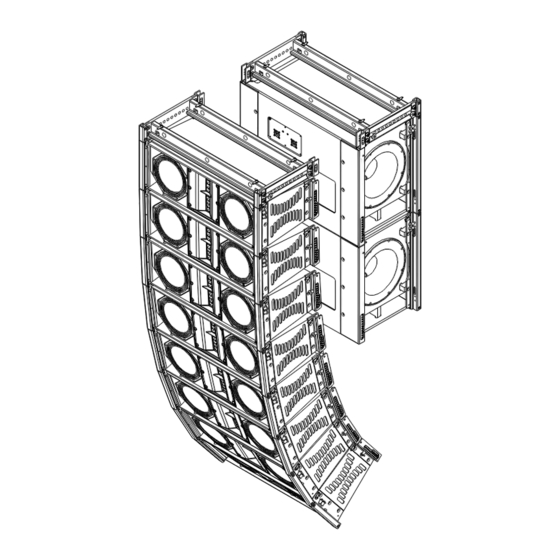
- Page 16 Coupler Beam XS212 Enclosures XLD281 Enclosures Front View Side View Figure 7a: Flying an Array of XS212’s behind XLD281’s using the XLVC Coupler Beam (audience only sees XLD281’s) ® ELECTRO-VOICE X-Line Very Compact Rigging Manual...
- Page 17 Enclosures Ground XLD281 Enclosures Front View Side View Front View Side View Figure 7b: Figure 7c: Flying an Array of XLD281’s under Groundstacking XLD281’s over XS212’s XS212’s using Interactive Rigging using Interactive Rigging ® ELECTRO-VOICE X-Line Very Compact Rigging Manual...
-
Page 18: Rigging-Strength Ratings, Safety Factors, And Special Safety Considerations
The working-load limits defined by the manufacturer of any rigging component should never be exceeded. Electro-Voice bases the working-load limits of its XLVC products on a minimum of an 8:1 safety factor. Other manufacturers of rigging components may base their working-load limits on safety factors other than 8:1. -
Page 19: Structural Rating Overview
3.3 Simplified Structural-Rating Guidelines Electro-Voice engineers have defined a set of simplified structural-rating guidelines that will en- able a rigger to immediately evaluate the safety of an XLVC system on site without having to make complex force-distribution calculations. A combination of destructive testing and computer modeling were used to analyze the complex forces throughout arrays. - Page 20 3. Angles of the force components on the front hinge bars and rigging tubes relative to the enclosures. 4. Angles of the force components on the rear swing arms, quick-release pins and rigging channels relative to the enclosures. Figure 8: Simplified XLVC Rigging-Rating Guidelines ® ELECTRO-VOICE X-Line Very Compact Rigging Manual...
- Page 21 However, in arrays where a pull-up grid is used to achieve substantial downward angles, it is possible that a lower enclosure could be the limiting factor. ® ELECTRO-VOICE X-Line Very Compact Rigging Manual...
-
Page 22: Complex Structural-Rating Analysis
It also should be noted that the XLVC rear rigging is only rated for use over side-to-side pull angles of a maximum of ±5°. ® ELECTRO-VOICE X-Line Very Compact Rigging Manual... - Page 23 -5° +5° -∅° +∅° Figure 9: XLD281, XLE181, and XS212 Front-Rigging-Point Structural Ratings ® ELECTRO-VOICE X-Line Very Compact Rigging Manual...
- Page 24 From +170° to +180° (XLD281, XLE181 - Swing Arm in Compression) From +160° to +180° (XS212 - Swing Arm in Compression) These are the Only Possible Angle Ranges Figure 10: XLD281, XLE181, and XS212 Rear-Rigging-Point Structural Ratings ® ELECTRO-VOICE X-Line Very Compact Rigging Manual...
- Page 25 Total Column Weight Working-Load Limit 850 lb (386 kg) Figure 11: XLD281, XLE181 and XS212 Overall Enclosure Structural Ratings ® ELECTRO-VOICE X-Line Very Compact Rigging Manual...
-
Page 26: Wind Loading
However, for the sake of simplicity, Electro-Voice chooses to define the work- ing-load limit of the overall enclosures as the sum total of the weight of that enclosure plus the weight of all of the enclosures and rigging hardware suspended below. -
Page 27: Electro-Voice Structural-Analysis Procedures
3.6 Electro-Voice Structural-Analysis Procedures Electro-Voice maintains a structural pull-test facility in Burnsville, Minnesota USA which includes load cells with digital-electronic display and recording. The load cells are calibrated annually by an independent laboratory to a standard traceable to the United States National Bureau of Standards. -
Page 28: Rigging Inspection And Precautions
Never exceed the limitations or maximum recommended load for the XLVC systems. Electro-Voice XLVC Front Rigging Hinge Bar Assemblies: Prior to each use, inspect the front rigging hinge bars and the front rigging tubes for any cracks, burrs, deformations, corrosion or missing or damaged components that could reduce hinge bar assembly strength. - Page 29 Replace any damaged mechanical components. Never exceed the limitations or maximum recommended load for the mechanical components. ® ELECTRO-VOICE X-Line Very Compact Rigging Manual...
-
Page 30: References
[12] J.E. Shigley & C.R. Mischke, Mechanical Engineering Design, McGraw-Hill Book Company, New York, NY, USA (1989). [13] A. Jensen & H.H. Chenoweth, Applied Engineering Mechanics, McGraw-Hill Book Com-pany, New York, NY, USA (1983). Websites [14] http://www.cmworks.com/ [15] http://catalog.thecrosbygroup.com/maininterface.htm ® ELECTRO-VOICE X-Line Very Compact Rigging Manual... -
Page 31: Notes
Notes ® ELECTRO-VOICE X-Line Very Compact Rigging Manual... - Page 32 For technical assistance, contact Technical Support at: 866/78-AUDIO Specifications subject to change without notice. All Other International Locations: 952-884-4051 Fax: 952-736-4212 www.electrovoice.com Telex Communications, Inc. www.telex.com Printed in U.S.A © Telex Communications, Inc. 2/2005 Part Number 38110-429 Rev 1 ® ELECTRO-VOICE X-Line Very Compact Rigging Manual...
Need help?
Do you have a question about the X-Line Very Compact and is the answer not in the manual?
Questions and answers