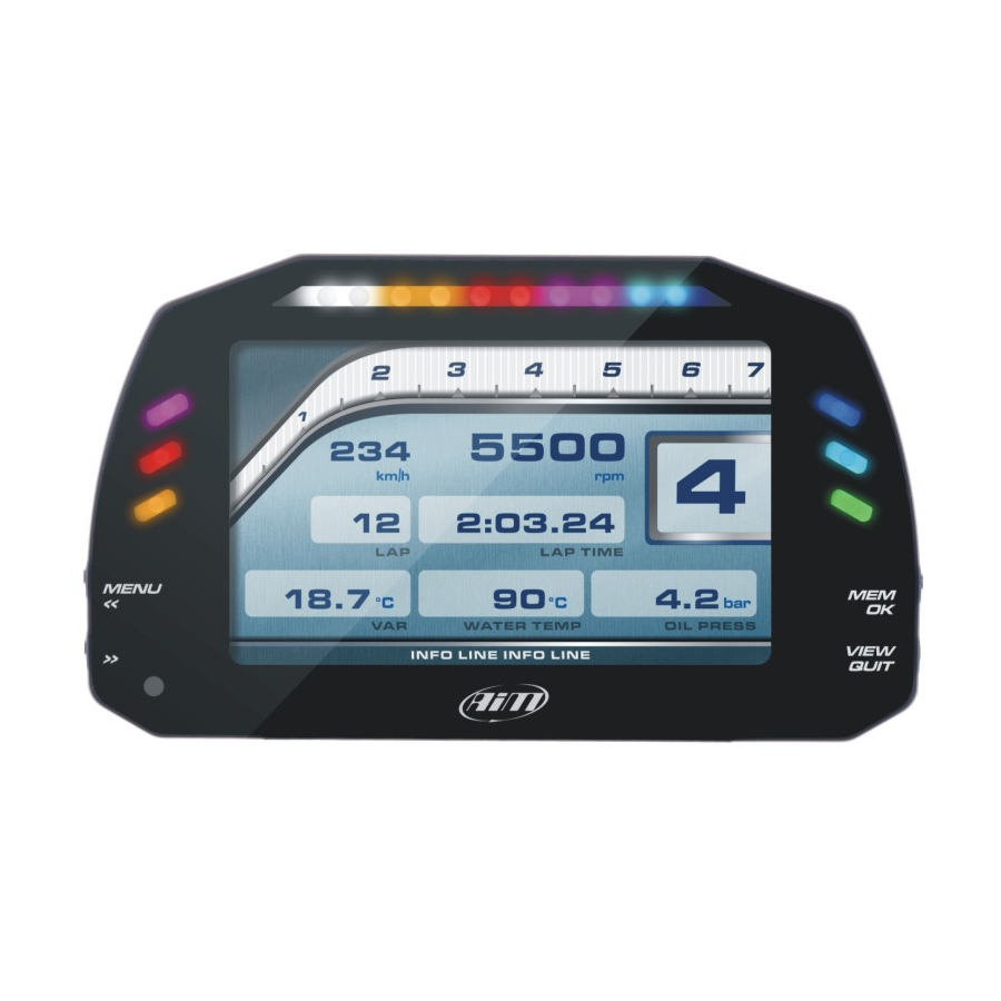
Aim MXG 1.2 Strada User Manual
Hide thumbs Also See for MXG 1.2 Strada:

Advertisement

Our web site aim-sportline.com is constantly
updated.
Please, constantly check it and download the
last versions of the firmware of your products.
Made in Italy
www.aim-sportline.com
MXG 1.2 Strada
MXP Strada
MXS 1.2 Strada
USER GUIDE 1.00

Advertisement

Table of Contents
loading
Need help?

Need help?

Do you have a question about the MXG 1.2 Strada and is the answer not in the manual?

Questions and answers

Summary of Contents for Aim MXG 1.2 Strada

  • Page 1 MXG 1.2 Strada MXP Strada MXS 1.2 Strada USER GUIDE 1.00 Our web site aim-sportline.com is constantly updated. Please, constantly check it and download the www.aim-sportline.com last versions of the firmware of your products. Made in Italy...
  • Page 2: Table Of Contents

    4 WHAT YOU CAN DO VIA KEYBOARD 4.1 SET DATE/TIME 4.2 SET BACKLIGHT 4.3 SET VIDEO INPUT MXG 1.2 Strada - MXP Strada - MXS 1.2 Strada 4.4 COUNTERS MANAGEMENT 4.5 GPS & TRACKS MANAGEMENT 4.6 SYSTEM INFORMATION 5 MX STRADA SERIES AND THE PC 5.1 CONNECTION TO THE PC...
  • Page 3: Mx Strada Series In A Few Words

    What is MX Strada Series? Is MX Strada Series an expandable device? MX Strada series is the new AiM dash that Yes. MX Strada series can be connected to combines small dimensions, flexibility, usa- various AiM expansions like GPS Module,...
  • Page 4: What Is In The Kit

    CHAPTER 2 MX STRADA SERIES 2. What is in the kit? MX Strada series kit includes: n MX Strada series standard version or with street icons as shown here below n USB cable n 14 pins connector harness for ECU connection and power; it is available in two versions: standard for ECUs communicating through CAN/RS232 protocol or with the OBDII connector for ECUs communicating with CAN/RS232 and K-Line.
  • Page 5 CHAPTER 2 MX STRADA SERIES MXS 1.2 Strada Dash Configurable Alarm LEDs 1-3 Shift Lights Configurable Alarm LEDs 4-6 AMP Connectors Aluminum Body Camera Input Multifunctional Pushbuttons...
  • Page 6: Powering

    CHAPTER 3 CHAPTER 4 MX STRADA SERIES 3 Powering 4 What you can do via keyboard The power is managed by two pins of the MX Strada series needs to be configured via 14 pins connector: software but there are some functions you can manage via the device lateral buttons.
  • Page 7: Set Date/Time

    CHAPTER 4 MX STRADA SERIES 4.1 Set Date/Time Press “Menu button and this page appears. Here you can: n set time zone n enable/disable Daylight saving time n set time and date format Bottom of the page current time and date are shown.
  • Page 8: Set Video Input

    CHAPTER 4 MX STRADA SERIES 4.3 Set video input 4.4 Counters management Video In page manages up to two additio- MX Strada series features 4 user odometers, nal optional back cameras (that cannot be labelled User 1 – User 4, plus a non-resetta- logged).
  • Page 9: Gps & Tracks Management

    CHAPTER 4 MX STRADA SERIES 4.5 GPS & Tracks management 4.6 System Information MX Strada series can be used on track thanks to the optional AiM GPS08 Module. This is used for: n Lap time calculation n Speed calculation n Predictive lap time calculation...
  • Page 10: Mx Strada Series And The Pc

    Channels: analog and digital sensors that directly connected to MX Strada series dash. n ECU: the Engine Control Unit of the vehicle. MX Strada series dash manages CAN, RS232 and Using AiM Race Studio 3 software you can configure MX Series, manage its tracks database as K-Line protocols well as check other device functions through Race Studio 3 device window.
  • Page 11: Channels Configuration

    CHAPTER 5 MX STRADA SERIES 5.2.1 Channels configuration The first two channels in the list are RPM and speed, follows the configurable channels that can be managed as analog or as digital according to what they are connected to. Typically analog sensors are pressure sensors, thermocouples, potentiometers, etc… while di- gital inputs are used for managing pushbuttons, that may be used for activating the digital To set all the channels.
  • Page 12 CHAPTER 5 MX STRADA SERIES n Active/Not active labels: according to the status, a Digital channel may assume the values: To use an input as “Digital Input” its parameters have to be configured as follows: 0/1, High/Low, ON/OFF, Closed/Open, True/False, etc. The two different labels can be defined and eventually shown on the display, used by Math channels, Icons Management, alarm managements and in general, any time a digital channel is required;...
  • Page 13: Ecu Connection And Configuration

    MX Strada series can be connected to the vehicle ECU. Documents explaining how to connect After setting the protocol the system comes back to “ECU Stream” page and two checkbox ap- MX Strada series to the ECU are published on our website www.aim-sportline.com and a PDF pears: n “Enable the CAN Bus 120 Ohm Resistor”...
  • Page 14: Can2 Stream Configuration

    5.2.3 CAN2 Stream configuration 5.2.4 CAN Expansions configuration This page works exactly like ECU Stream one. Here are additional CAN modules. To load one: MX Strada series can be connected to various AiM CAN expansions: n enter “CAN2 Stream” tab n LCU-One CAN n press “Change protocol”...
  • Page 15 “Close” to save and exit n press “Close” to save and exit Please note: for any further information about AiM LCU-One CAN refer to the related user ma- Please note: for any further information about AiM Channel expansion refer to the related user...
  • Page 16: Math Channels Configuration

    Each option asks the user to fill in a proper panel. Please note: for any further information about AiM TC Hub refer to the related user manual you can download from AiM website...
  • Page 17: Status Variables Configuration

    CHAPTER 5 MX STRADA SERIES 5.2.6 Status variables configuration Status Variables are internal math channels that can have only two different values: 1 (TRUE) In order to define a Status Variable enter the proper TAB. or 0 (FALSE). They may be useful for simplifying complex configurations, where it is required to evaluate if to activate alarms, LEDs, Icons etc..
  • Page 18: Parameters Configuration

    CHAPTER 5 MX STRADA SERIES 5.2.7 Parameters configuration To set the beacon. Mousing over the question marks a pop up message explains the working mode of: n GPS Beacon (needs an optional GPS08 Module): hold lap time for: the time period for which lap time is shown on your MX Strada series display the track width: width that will be considered for any GPS point you set n CAN Optical beacon (not recommended):...
  • Page 19: Shift Lights And Alarms Configuration

    CHAPTER 5 MX STRADA SERIES 5.2.8 Shift Lights and Alarms configuration To set shift lights (on top) and alarm LEDs (bottom) of your MX Strada series. On top MX Strada series shift lights working mode can be set. Available options are: n shift lights, for helping in changing gear and n predictive time: for easily understanding if the current lap is faster or slower than the reference lap.
  • Page 20 CHAPTER 5 MX STRADA SERIES Use for predictive time. Create and set MX Strada series alarm Click the icon ( ) for setting the parameters. To create a new alarm press “Add New Alarm” and the related panel shows up. In this case the LEDs colour are fixed in: n Green if the lap time is improving n Red if the lap time is worse than the reference lap...
  • Page 21: Trigger Commands Configuration

    CHAPTER 5 MX STRADA SERIES To set the new alarm: 5.2.9 Trigger commands configuration n define the Alarm name (1) n a combination of Alarm conditions can be set: choose if the conditions are to be ALL valid or just one of them (2-4) n decide which action is to be trigged (5) among displaying a message or a timed popup “Trigger Command”...
  • Page 22 CHAPTER 5 MX STRADA SERIES n decide the action to be performed (5) In the Trigger Commands summary page, trigger command can be modified/deleted right n Click “Save” clicking on the setting icon placed right of the trigger row.
  • Page 23: Icons Manager Configuration

    CHAPTER 5 MX STRADA SERIES 5.2.10 Icons manager configuration The “Icon” is a set of images, each one of them to be shown on each page as desired, that To configure an Icon n press “Add New Icon” depend on a fixed condition that, when exists, triggers the proper image. n “Manage Icon”...
  • Page 24: Display Configuration

    CHAPTER 5 MX STRADA SERIES 5.2.11 Display configuration The “Icons page” shows a summary of the selected icons. If you mouse over any icon, a panel MX Strada series can have up to eight pages to be set via software. with all the information appears.
  • Page 25: Smartycam Stream Setting

    When the page has been selected two setting panels appear bottom of the page: MX Strada series can be connected to AiM SmartyCam to show the desired data on SmartyCam n on the left a panel that shows as many rows as the fields to be set video.
  • Page 26: Can Output Configuration

    CHAPTER 5 MX STRADA SERIES To add a payload: 5.2.13 CAN Output configuration n press “+Add new Payload” and “Set CAN Header details” appears; n fill in ID CAN (hex), available options are: 11 bits (normal address) Please note: this function is for expert users only. 29 bits (extended address) n select the payload max bytes number (DLC ), available options are from 1 to 8 bytes n select the byte order according to the used processor, available options are:...
  • Page 27: Managing A Track On Mx Strada Series With Race Studio

    CHAPTER 5 MX STRADA SERIES The main page is divided in three columns; on the left: n on top, the filters that allow to collect many tracks following customized criteria; by default, all tracks are shown (light blue “All Tracks” filter in the image below). n bottom left, the connected devices in the image, “MXS Strada ID 5302808”) The column in the middle shows: n on top a fast search bar, that allows to select the tracks which satisfy your personal research...
  • Page 28 Tracks created by the user are labelled “User” and if the track stored in MX Strada series dash is different from the one stored on AiM database this is notified as shown here above. be loaded to another AiM device n Load Saved: load the tracks previously saved in the device memory The page keyboards are used to manage the tracks.
  • Page 29: Ecu Driver Builder

    “OK” and a new CAN Driver has been added fill in “Edit new model name” box. For further information about how to set the new CAN Driver refer to the CAN Driver builder user manual downloadable from www.aim-sportline.com, documentation area software/fir- mware section.
  • Page 30: The Device Window

    CHAPTER 5 MX STRADA SERIES 5.5 The device window 5.5.1 Live measures layer Once the configuration has been transmitted “Live Measures” page shows ECU Channels too and some operations can be performed, like start recording and stop live measures as well as making the device blinking pressing the button top right of the page.
  • Page 31: On The Track

    CHAPTER 5 CHAPTERS 6 7 MX STRADA SERIES 6 On the track As shown in the image below, once the values have been forced they are shown right of the MX Strada series can show up to eight pages. To scroll them press “>>” lateral button. Pages page hedged in red.
  • Page 32: New Firmware Upgrade

    CHAPTER 7 CHAPTER 8 MX STRADA SERIES 8 New firmware upgrade Third is“Summary”page that shows all tests Our technicians and engineers are constantly working to improve both the firmware (the ap- in a box with time of the test, number of plication that manages the device) and the software (the application installed on the PC).
  • Page 33: Rpm

    CHAPTER 9 MX STRADA SERIES 9 RPM In case the vehicle ignition system has no output MX Strada series dash should be connected to the low voltage of the coil as shown in the following images. MX Strada series dash can receive RPM value from the ECU. If on the contrary the vehicle does not have an ECU RPM can be sampled using the wire labelled “RPM”...
  • Page 34: Connection With The Expansions

    10 Connection with the expansions 10.1 Rear cameras connection and management MX Strada series can be connected to AiM GPS08 Module, LCU-One CAN, Channel expansion, MX Strada Series dashes can manage rear cameras through the 5 pins Binder 712 female con- TC Hub, SmartyCam HD and SmartyCam GP HD in order to improve its functionality.
  • Page 35 To perform the command on the logger press “MENU” button and scroll up to “VIDEO IN”. dashes and patch cables for connecting most of them are available. Please refer to our website www.aim-sportline.com for more information about them. Please note: rear camera dimensions and MX Strada series camera input pinout are shown in chapter 11.
  • Page 36: Technical Specifications And Drawings

    Metallic Connectors 2 AMP connectors + 1 Binder connector Body Anodized Aluminum Weight 480g (MXS 1.2 Strada) – 640g (MXP Strada) – 950g (MXG 1.2 Strada) Dimensions 169.4x97x23mm (MXS 1.2 Strada) - 189.6x106.4x24.9mm (MXP Strada) 237x127.6x26mm (MXG 1.2 Strada) Waterproof...
  • Page 37 CHAPTER 11 MX STRADA SERIES MXP Strada dimensions in mm [inches] MXG 1.2 Strada dimensions in mm [inches]...
  • Page 38 CHAPTER 11 MX STRADA SERIES MX Strada Series pinout...
  • Page 39 CHAPTER 11 MX STRADA SERIES MX Strada series 14 pins AMP connector harness – standard version...
  • Page 40 CHAPTER 11 MX STRADA SERIES MX Strada series 23 pins AMP connector harness...
  • Page 41 CHAPTER 11 MX STRADA SERIES MX Strada series 14 pins AMP connector harness with OBDII connector...
  • Page 42 CHAPTER 11 MX STRADA SERIES MX Strada Series USB Cable MX Strada series mirror camera input...
  • Page 43 CHAPTER 11 MX STRADA SERIES Mirror camera dimensions in mm [inches] MX Strada series cable for single AiM mirror camera...
  • Page 44 CHAPTER 11 MX STRADA SERIES MX Strada series cable for n.2 AiM mirror cameras MX Strada series cable for single non AiM mirror camera...
  • Page 45 CHAPTER 11 MX STRADA SERIES MX Strada series cable for n.2 non AiM mirror camera Our web site aim-sportline.com is constantly updated. Please, constantly check it and download the last versions of the firmware of your products.

This manual is also suitable for:

Mxs 1.2 stradaMxp strada

Table of Contents