Advertisement
Quick Links
DSNU/CRDSNU
Round cylinder
Instructions | Operating
8094773
2018-07a
[8094775]
Translation of the original instructions
1
Further applicable documents
All available documents for the product è www.festo.com/pk.
2
Safety
2.1
Allgemeine Sicherheitshinweise
–
Take into consideration the ambient conditions at the location of use.
–
Only use the product in original status without unauthorised modifications.
–
Observe labelling on the product.
–
Observe further applicable documents.
–
Store the product in a cool, dry, UV-protected and corrosion-protected envir-
onment. Ensure that storage times are kept to a minimum.
–
Prior to mounting, installation and maintenance work: Switch off compressed
air supply and secure it from being switched back on.
–
Observe tightening torques. Unless otherwise specified, the tolerance
is ± 20 %.
2.2
Intended use
The product is intended for the transport of loads.
2.3
Training of skilled personnel
Installation, commissioning, maintenance and disassembly should only be con-
ducted by qualified personnel.
3
Further information
–
Accessories è www.festo.com/catalogue.
–
Spare parts è www.festo.com/spareparts.
4
Service
Contact your regional Festo contact person if you have technical questions
è www.festo.com.
4.1
Function
The piston rod moves outwards when the cylinder chamber is pressurised. The
advanced piston rod is retracted as follows:
–
For single-acting cylinders, by means of the integrated return spring.
–
For double-acting cylinders, by pressurising the other cylinder chamber.
The cylinder force during advance and return is:
–
Different with piston rod at one end
–
Identical with piston rod at both ends
The position of the piston can be sensed by proximity sensors.
4.2
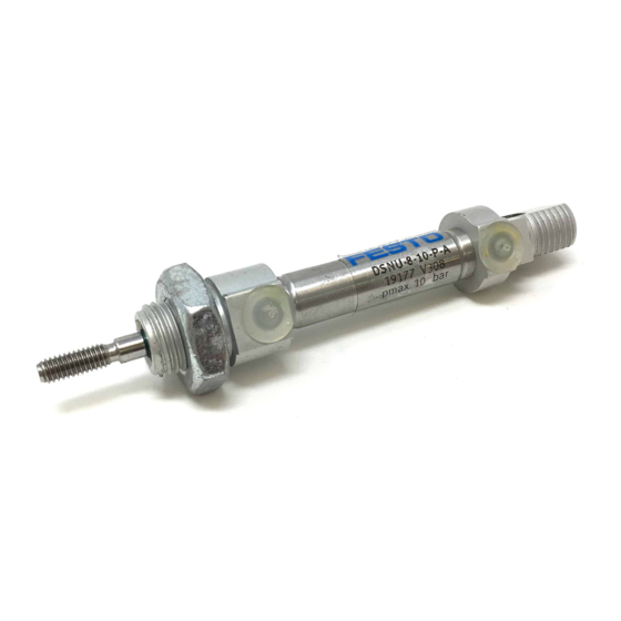
DSNU
Festo AG & Co. KG
Ruiter Straße 82
73734 Esslingen
Germany
+49 711 347-0
www.festo.com
8094773
1 Male thread on the piston rod for
mounting the payload
2 Male thread on the bearing cap for
mounting
Fig. 1 Design of DSNU
CRDSNU
1 Male thread on the piston rod for
mounting the payload
2 Male thread on the bearing cap for
mounting
Fig. 2 Design of CRDSNU
4.3
•
Handle the cylinder so as to avoid any damage to the cylinder barrel and pis-
ton rod.
•
Observe the following points:
–
–
–
•
Observe tightening torque of lock nuts on the male thread 2
è Tab. 1 Tightening torque on the bearing/end cap.
Size
DSNU
Tightening torque
on the bearing cap
Tightening torque
on the end cap
CRDSNU
Tightening torque
on the bearing cap
Tab. 1 Tightening torque on the bearing/end cap
•
Avoid mechanical alignment inaccuracies between the piston rod and an
external guide using one of the following measures:
–
–
–
A rigid coupling impairs the service life and function of the cylinder.
4.4
In the case of a large payload, high piston speed or when using quick exhaust
valves:
Design
Installation
Parallel installation when using external guides
Warp-free installation
Compliance with the permissible loads as per catalogue specifications
8
10
12
[Nm]
10
10
20
[Nm]
4.6
4.6
10.8 10.8 20.7 20.7 21.5 25.1 30.9 30.9
[Nm]
–
15
Absolutely precise alignment (general)
Use of a self-aligning rod coupler FK
Use of a guide unit FEN with compensating coupling
Mounting accessories
3 Supply ports in the bearing/end
cap
4 Cross hole for mounting
5 Male thread on the end cap for
mounting
3 Supply ports in the bearing/end
cap
4 Cross hole for mounting
16
20
25
32
40
50
20
40
40
60
80
100
15
40
40
60
80
100
63
100
100
Advertisement

Related Manuals for Festo DSNU-8


Summary of Contents for Festo DSNU-8
- Page 1 – Spare parts è www.festo.com/spareparts. mounting Fig. 2 Design of CRDSNU Service Contact your regional Festo contact person if you have technical questions Installation è www.festo.com. • Handle the cylinder so as to avoid any damage to the cylinder barrel and pis- Function ton rod.
- Page 2 Remedy stroke Irregular movement of the pis- Lack of lubricant. Grease with lubricant (as per Tab. 3 Technical data for DSNU-8 to DSNU-25 ton rod (cylinder jolts). wearing parts sheet è www.festo.com/spareparts One-way flow control valves are Control flow of exhaust air, if controlling the flow of supply possible (not supply air).
- Page 3 DSNU-32 … 63 Size Pneumatic connection G1/8 G1/4 G3/8 Piston rod thread M10x1.25 M12x1.25 M16x1.5 End-position cushioning Elastic cushioning rings/plates, at both ends (P cushion- ing) Pneumatic cushioning, can be adjusted at both ends (PPV cushioning) Pneumatic cushioning, self-adjusting at both ends (PPS cushioning) Mounting position Operating medium...