Table of Contents
Advertisement
CONTENTS
SAFETY CONSIDERATIONS . . . . . . . . . . . . . . . . . . . . . . 1
INTRODUCTION . . . . . . . . . . . . . . . . . . . . . . . . . . . . . . . . . . 2
INSTALLATION . . . . . . . . . . . . . . . . . . . . . . . . . . . . . . . . 2-18
Step 1 - Complete Pre-Installation Checks . . . . . . 2
Step 2 - Locate and Rig Unit, Remove
Shipping Skid . . . . . . . . . . . . . . . . . . . . . . . . . . . . . . . . . . 2
• LOCATION
• RIGGING
• PLACING UNIT
• MOUNTING UNIT
Step 3 - Complete Refrigerant Piping . . . . . . . . . . . 6
• GENERAL
Step 4 - Complete Electric Connections. . . . . . . . 18
• GENERAL
• CONNECTIONS
Step 5 - Add Accessories as Needed. . . . . . . . . . . 18
START-UP . . . . . . . . . . . . . . . . . . . . . . . . . . . . . . . . . . . . 18-20
System Evacuation and Dehydration . . . . . . . . . . . . 18
Charging Procedure . . . . . . . . . . . . . . . . . . . . . . . . . . . . . 18
Controls and Rotation of Fans . . . . . . . . . . . . . . . . 18
SERVICE . . . . . . . . . . . . . . . . . . . . . . . . . . . . . . . . . . . . . 21,22
Fan Guard Removal . . . . . . . . . . . . . . . . . . . . . . . . . . . . . 21
Fan Adjustment . . . . . . . . . . . . . . . . . . . . . . . . . . . . . . . . . 21
Lubrication . . . . . . . . . . . . . . . . . . . . . . . . . . . . . . . . . . . . . . 21
Cleaning Standard Coils. . . . . . . . . . . . . . . . . . . . . . . . . 21
Cleaning and Maintaining E-Coated Coils . . . . . . . 21
Fan Motor Removal. . . . . . . . . . . . . . . . . . . . . . . . . . . . . . 22
Head Pressure Control . . . . . . . . . . . . . . . . . . . . . . . . . . 22
• FAN CYCLING
SAFETY CONSIDERATIONS
Installing, starting up, and servicing air-conditioning equip-
ment can be hazardous due to system pressures, electrical com-
ponents and equipment location (roofs, elevated structures,
etc.).
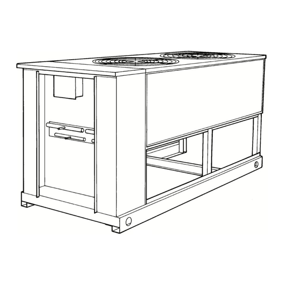
Only trained, qualified installers and service mechanics
should install, start up, and service this equipment (Fig. 1).
Untrained personnel can perform basic maintenance func-
tions such as cleaning coils. All other operations should be per-
formed by trained service personnel.
Manufacturer reserves the right to discontinue, or change at any time, specifications or designs without notice and without incurring obligations.
Catalog No. 530-917
Printed in U.S.A.
Installation, Start-Up and
Service Instructions
Page
Form 09DK-13SI
Air-Cooled Condenser Units
When working on the equipment, observe precautions in the
literature and on tags, stickers, and labels attached to the
equipment.
Follow all safety codes. Wear safety glasses and work
gloves. Keep quenching cloth and fire extinguisher nearby
when brazing. Use care in handling, rigging, and setting bulky
equipment.
ELECTRIC SHOCK HAZARD
Open all remote disconnects before servicing
this equipment.
DO NOT USE TORCH to remove any component. System
contains oil and refrigerant under pressure.
To remove a component, wear protective gloves and gog-
gles and proceed as follows:
a. Shut off electrical power to unit.
b. Recover refrigerant to relieve all pressure from sys-
tem using both high-pressure and low pressure ports.
c. Traces of vapor should be displaced with nitrogen
and the work area should be well ventilated. Refrig-
erant in contact with an open flame produces toxic
gases.
d. Cut component connection tubing with tubing cutter
and remove component from unit. Use a pan to catch
any oil that may come out of the lines and as a gage
for how much oil to add to the system.
e. Carefully unsweat remaining tubing stubs when nec-
essary. Oil can ignite when exposed to torch flame.
Failure to follow these procedures may result in personal
injury or death.
DO NOT re-use compressor oil or any oil that has been
exposed to the atmosphere. Dispose of oil per local codes
and regulations. DO NOT leave refrigerant system open to
air any longer than the actual time required to service the
equipment. Seal circuits being serviced and charge with
dry nitrogen to prevent oil contamination when timely
repairs cannot be completed. Failure to follow these proce-
dures may result in damage to equipment.
Pg 1
612
09DK020-044
50/60 Hz
11-99
Replaces: 09DK-11SI
Advertisement
Table of Contents

Subscribe to Our Youtube Channel
Related Manuals for Carrier 09DK Series


Summary of Contents for Carrier 09DK Series
-
Page 1: Table Of Contents
09DK020-044 Air-Cooled Condenser Units 50/60 Hz Installation, Start-Up and Service Instructions When working on the equipment, observe precautions in the CONTENTS literature and on tags, stickers, and labels attached to the Page equipment. SAFETY CONSIDERATIONS ..... . 1 Follow all safety codes. -
Page 2: Introduction
If overhead rigging is not possible, place unit on skid or pad INTRODUCTION for rolling or dragging. When rolling, use minimum of 3 roll- These instructions describe installation, start-up, and serv- ers. When dragging, pull the pad. Do not apply force to the ice of 09DK020-044 air-cooled condensers (Fig. - Page 3 DIMENSIONS — MM [FT-IN.] UNIT 09DK 1131 1007 020,024 [3-8 [3-3 [1-0] [0-9] [1-10] 1742 1619 [5-8 [5-3 [1-7 [3-0] [1-5 [2-6] NOTES: 1. There must be 1220 mm [4-0] for service and for unrestricted airflow on all sides of unit. 2.
- Page 4 DIMENSIONS — MM [FT-IN.] UNIT 09DK [1-2 [1-7 [3-0] [1-5 [2-6] NOTES: 1. There must be 1220 mm [4-0] for service and for unrestricted airflow on all sides of unit. 2. There must be minimum 2440 mm [8-0] clear air space above unit. 3.
- Page 5 COIL CONNECTION DIMENSIONS — MM [IN.] UNIT 09DK 34.9 I.D. 28.5 I.D. 22.2 I.D. 15.9 I.D. NOTE #5 NOTES: 1. There must be 1220 mm [4-0] for service and for unrestricted airflow on all sides of unit. 2. There must be minimum 2440 mm [8-0] clear air space above unit. 3.
-
Page 6: Step 3 - Complete Refrigerant Piping
The following sections describe how to modify the standard revision. unit circuiting (as shipped from the factory) for optional splits. For leak testing procedures, refer to the Carrier Refrigerant NOTE: All coils are purged with dry air and then capped prior Service Techniques Manual. - Page 7 09DK020,024 67/33% Circuiting Modification — To con- a. Cap the open stub tubes on the left headers, where vert the 09DK020 or 09DK024 coil from the 50/50% to two are located on the gas header, and one on the 67/33% circuiting, perform the following steps: liquid header.
- Page 8 09DK028,034 60/40% Circuiting Modification — To con- a. Cap the open stub tubes on the left headers, where vert the 09DK028 or 09DK034 coil from the 50/50% to two are located on the gas header, and one on the 60/40% circuiting, perform the following steps: liquid header.
- Page 9 09DK028,034 40/40/20% Circuiting Modification — To a. Cap the open stub tubes on the left and right gas convert the 09DK028 or 09DK034 coil from the 50/50% to and liquid headers with stub tube caps supplied in 40/40/20% circuiting, perform the following steps: the parts kit.
- Page 10 Construct 2 gas “U” tube assemblies (Item B), piping diameter. Refer to Carrier System Design consisting of the following parts, and braze them Manual, Part 3, for hot gas and liquid pipe sizing into the gas headers as shown.
- Page 11 -in. OD nipples (cut to length as required) opening is dependent upon interconnecting system piping diameter. Refer to Carrier System Design b. Construct the 26% gas tubing assembly (Item B), Manual, Part 3, for hot gas and liquid pipe sizing consisting of the following parts, and braze it into information.
- Page 12 NOTE: Diameter of tee’s interconnecting pipe while protecting adjacent joints from heat. opening is dependent upon interconnecting system piping diameter. Refer to Carrier system Design a. Construct the 66% gas tubing assembly (Item A), Manual, Part 3 for hot gas and liquid pipe sizing consisting of the following parts, and braze it into information.
- Page 13 NOTE: Diameter of tee’s interconnecting pipe while protecting adjacent joints from heat. opening is dependent upon interconnecting system piping diameter. Refer to Carrier System Design a. Construct the 60% gas tubing assembly (Item A), Manual, Part 3 for hot gas and liquid pipe sizing consisting of the following parts, and braze it into information.
- Page 14 09DK044 53/47% Circuiting Modification — To config- c. Construct the 47% gas tubing assembly (Item C), ure the 09DK044 for two refrigerant circuits (one with 53% consisting of the following parts, and braze it into capacity and one with 47% capacity) using field supplied gas headers as shown in Fig.
- Page 15 09DK044 40/13/13/34% Circuiting Modification — To con- b. Plug the open -in. stub tubes at the inside of figure the 09DK044 for four refrigerant circuits (one with each of the large gas headers as shown in Fig. 17, 40% capacity, two with 13% capacity, and one with 30% Item B.
-
Page 16: Refrigerant Line Sizing
3. Refer to Carrier System Design Manual, part 3 for proper pip- ing sizes and design. 4. For piping lengths greater than 50 ft (15.2 m), provide support to liquid and gas lines near the connections to the coil. -
Page 17: Coil Connections
3. Refer to Carrier System Design Manual, part 3 for proper piping sizes and design. 4. For piping lengths greater than 50 ft (15.2 m), provide support to liquid and gas lines near the connections to the coil. -
Page 18: Step 4 - Complete Electric Connections
Reclamation” and Carrier Refrigerant Service Techniques damage may not be covered by Carrier warranty. manual for proper charging techniques. Add 10 lbs (4.5 kg) of R-22 over clear sight glass to flood subcooler sections of the All wiring must be in accordance with NEC (National Elec- condenser coils. - Page 19 Table 3 — 09DK Electrical Data 60 HERTZ UNIT FAN MOTORS CONTROL CIRCUIT UNIT Supplied Volts MOCP 09DK Volts -3 Ph FLA (ea) Volts -1 Ph Amps (Fuse) 208/230 14.8 208/230 14.8 208/230 13.9 208/230 21.4 12.7 10.7 11.0 208/230 20.1 12.7 10.1...
- Page 20 Table 4 — Refrigerant Circuit Data UNIT 09DK 020, 024 COIL No. of Ckts Cap. (% Ckt) REFRIGERANT Min. Operating Chg/Ckt* 10.6 14.1 11.8 14.1 17.5 21.0 14.0 14.0 Optimum Operating Chg/Ckt† 11.2 12.5 16.6 13.8 16.6 11.1 11.1 20.6 24.8 16.5 16.5...
-
Page 21: Service
spraying coil from inside. Condenser fan motors are drip-proof SERVICE but not waterproof. Routine cleaning of coil surfaces is essen- On all sizes, remove eight Fan Guard Removal — tial to minimize contamination build-up and remove harmful 14 x -in. long self-tapping hex head screws per guard and residue. -
Page 22: Fan Motor Removal
E-COAT ENZYME CLEANER APPLICATION INSTRUCTIONS — Perform the following procedure to clean the coil. Do not use bleach, harsh chemicals, or acid cleaners on NOTE: Wear proper eye protection such as safety glasses outdoor or indoor coils of any kind. These types of cleaners during mixing and application. - Page 24 CALL FOR FREE CATALOG 1-800-644-5544 [ ] Packaged Service Training [ ] Classroom Service Training Copyright 1999 Carrier Corporation Manufacturer reserves the right to discontinue, or change at any time, specifications or designs without notice and without incurring obligations. Catalog No. 530-917 Printed in U.S.A.
Need help?
Do you have a question about the 09DK Series and is the answer not in the manual?
Questions and answers