
Related Manuals for Baker Ruskinn Concept-M


Summary of Contents for Baker Ruskinn Concept-M
- Page 1 User Manual UM-039 Concept-M Anaerobic and Microaerophilic Workstation Concept-M 400 / Concept-M 500 Affix Serial Number Sticker Here...
-
Page 2: Table Of Contents
Unit 8&9 / York Park / Bridgend, United Kingdom / CF31 3TB +44 (0) 1656 645688 / Fax: +44 (0) 1656 667966 / sales@ruskinn.com www.bakerruskinn.com CONTENTS TABLE OF FIGURES ......................III TABLE OF SCREEN IMAGES ..................... IV TABLE OF SCREEN ICONS ....................IV TABLE OF TABLES ...................... - Page 3 Unit 8&9 / York Park / Bridgend, United Kingdom / CF31 3TB +44 (0) 1656 645688 / Fax: +44 (0) 1656 667966 / sales@ruskinn.com www.bakerruskinn.com WORKSTATION ENTRY ....................21 WORKSTATION EXIT ....................23 HUMIDITY CONTROL ....................24 SCREENS ........................26 MAIN SCREEN ......................
-
Page 4: Table Of Figures
Unit 8&9 / York Park / Bridgend, United Kingdom / CF31 3TB +44 (0) 1656 645688 / Fax: +44 (0) 1656 667966 / sales@ruskinn.com www.bakerruskinn.com TABLE OF FIGURES Figure 1: Concept Rear Connections ................7 Figure 2: Gas Connection Graphic ..................8 Figure 3: Standard Concept Workstation with SPES Option.......... - Page 5 Unit 8&9 / York Park / Bridgend, United Kingdom / CF31 3TB +44 (0) 1656 645688 / Fax: +44 (0) 1656 667966 / sales@ruskinn.com www.bakerruskinn.com TABLE OF SCREEN IMAGES Screen 1: Interlock Purge Options .................. 16 Screen 2: Interlock Purge Timer ..................16 Screen 3: Main Menu .....................
-
Page 6: Introduction
INTRODUCTION Please read this manual carefully before using the Concept and familiarise yourself with all aspects of using the workstation. The Baker Company (Baker) or Ruskinn Technology Ltd (Ruskinn) does not accept responsibility for accidents to personnel or damage to the Concept workstation resulting from incorrect use. -
Page 7: Safety Instructions
SAFETY INSTRUCTIONS Baker and/or Ruskinn do not take any responsibility for damages caused by using the equipment for other purposes than described in this user manual. The mains appliance coupler and plug are the AC mains supply isolation device and must be easily accessible when installed. -
Page 8: Regulatory Compliance
REGULATORY COMPLIANCE European Region This product complies with the essential EEA requirements for Electrical Safety and Electromagnetic compatibility as set out in the EMC Directive 2014/30/EU, the Low Voltage Directive 2014/35/EU and hazardous substances (RoHS) Directive 2011/65/EU has been tested and found to comply in full. For details on standards tested refer to the DoC Certificate WEEE: This equipment must be disposed of in accordance with the Waste from Electrical and... -
Page 9: North American Region
North American Region This product is UL 61010-1 Listed, and CSA C22.2 No. 61010-1 under file number E113911. This equipment has been tested and found to comply with the limits for a Class A digital device, pursuant to part 15 of the FCC Rules. These limits are designed to provide reasonable protection against harmful interference when the equipment is operated in a commercial environment. -
Page 10: Symbols
Symbols Before using the Concept, please ensure that you are familiar with the symbols. Symbol Meaning Refer to user manual. Alternating current Functional Earth Connection Protective Earth Connection This product complies with the essential EEA requirements for Electrical Safety and Electromagnetic compatibility as set out in the EMC directive 2004/108/EC and the Low Voltage Directive 2006/95/EC Caution, do not remove covers. -
Page 11: Transport And Storage
TRANSPORT AND STORAGE When not in use, the Concept Workstation must only be stored within a temperature of between 0°C and 30°C Storage outside of this range may damage the workstation. LOCATION AND HANDLING OF THE CONCEPT WORKSTATION The Concept should only be installed or relocated by a qualified engineer. To arrange installation or relocation please contact your local distributor. -
Page 12: Service Requirements
SERVICE REQUIREMENTS Electrical Supply Requirements The workstation must be connected to a mains power supply. A power cord is supplied to connect the workstation to the mains supply. If an alternative power cord is used is must be rated appropriately for the power requirements of the workstation, refer to Table 2. The workstation must be connected to a protective earth. -
Page 13: Gas Supply Requirements
Table 3: Fuse Ratings Gas Supply Requirements The workstation gas supplies are located at the rear of the unit as shown in Figure 1. For standard physiological environment operation of the workstation the input gas requirements are: Regulator Output Symbol Specification Pressure 58 to 72.5psi... -
Page 14: Concept Overview
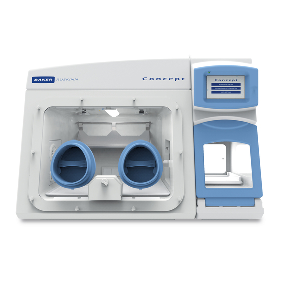
CONCEPT OVERVIEW Front View The Standard and Large Concept workstations are shown below in Figure 3 and Figure 4 respectively. Figure 3: Standard Concept Workstation with SPES Option Figure 4: Large Concept Workstation 1. Ezeeyin Glove Ports 2. Single Plate Entry System (SPES) (Optional Accessory) 3. -
Page 15: Front Interior Views
Front Interior Views Figure 5: Right Side Internal View Figure 6: Left Side Internal View 1. Internal Light 2. Temperature and Humidity Sensor Housing 3. Internal interlock door 4. Internal sockets 5. Condensate plate 6. Universal Port (Optional) 7. Waste Port (Optional) Glove Port Cap Stowage Page 10 of 50... -
Page 16: Left Side View
Left Side View Figure 7: Left Side End Panel with Ultrasonic Humidity Option 1. Lid – Service access only 2. Humidity water tank (optional) 3. Side Panel – Service access only 4. Cooling vent – Do not obstruct 5. Universal Port (Optional) Page 11 of 50... -
Page 17: Right Side View
Right Side View Figure 8: Right Side End Panel 1. Cooling vent – Do not obstruct 2. Side Panel – Service access only Page 12 of 50... -
Page 18: Rear View
Rear View Figure 9: Rear End Panel and Supply Connections Figure 10: Gas and Electrical Connections 1. Safety Label 2. Rear panel – Service access only 3. Ethernet Port (For use with Remote Monitoring Option Only) See Service Requirements section for further details on electrical and gas connections. Page 13 of 50... -
Page 19: Using The Workstation
USING THE WORKSTATION Using the interlock The Concept 400 workstation has a 26 litre interlock and the Concept 500 has a 41 litre interlock. This is used for transferring materials and samples into and out of the workstation chamber and pre-conditioning the atmosphere to not affect the internal workstation atmosphere. -
Page 20: Operating The Interlock Inner Door
Operating the interlock inner door The interlock inner door can only be opened if the interlock has been purged, indicated on the touchscreen, and the inner door push button being illuminated. To open the interlock inner door: Access the workstation chamber via the Ezeeyin glove ports after putting your arm through the Ezee-Sleeves. -
Page 21: Screen 1: Interlock Purge Options
Fast Purge 0% Purge Screen 1: Interlock Purge Options The interlock cycle status purge timer will appear on the touchscreen and count down the time remaining to achieve the set Oxygen level. Screen 2: Interlock Purge Timer Access the workstation chamber via the Ezeeyin glove ports after putting your arm through the Ezee-Sleeves. -
Page 22: Removing Material From The Workstation Chamber Via The Interlock
Removing material from the workstation chamber via the interlock To remove material from the workstation chamber via the interlock; Open the interlock inner door by pressing the inner door button and sliding the interlock inner door backwards. Move the material from the workstation chamber into the interlock chamber. ... -
Page 23: Hand Access To The Main Chamber
Hand access to the main chamber Direct hand access to the workstation chamber is provided via the Ezeeyin glove ports and Ezee-Sleeve The Ezee-Sleeve consists of a gloveless gas tight sleeve and a cuff. The Ezee-Sleeve attaches to the glove port via two O-rings. Note: The workstation should not be used without the Ezee-Sleeve or EzeeCuff attached. -
Page 24: Vacuum Operation
Vacuum Operation To ensure that no external atmosphere contaminates the workstation, a single vacuum operation is required before Glove Port access. To minimise the time, it is recommended to eliminate as much external atmosphere from the Ezee-Sleeve as possible prior to arm entry. -
Page 25: Figure 14: Foot Pedals For Right And Left Glove Ports
While the arm is grasping the handle, generate a vacuum by operating the foot pedal for the corresponding glove port. Figure 14: Foot pedals for right and left glove ports The vacuum operation should be continued until the maximum amount of external atmosphere has been removed from the Ezee-Sleeve and the Ezee-Sleeve exerts some pressure on the arm/hand. -
Page 26: Workstation Entry
Workstation Entry Once the vacuum has been achieved, the Glove Port Handle can now be rotated in either direction to unlock the Glove Port Cap. As there is a strong vacuum within the Ezee-Sleeve, removal of the Cap can require a reasonable amount of force. -
Page 27: Figure 19: Glove Port Cap Storage Location Inside Workstation
Figure 19: Glove port cap storage location inside workstation Repeat the procedure for the other hand (if both hands are entering the workstation chamber). Page 22 of 50... -
Page 28: Workstation Exit
Workstation Exit Remove Cap from storage brackets, and ensure the handle is oriented in a vertical position on the Cap. The Handle is designed with “indexing” detent features to help locate the Handle relative to the Cap. Drawing the handle into the Glove Port, replace the cap, using the location posts and graphic to orient the Cap correctly on the Glove Port. -
Page 29: Humidity Control
Humidity Control The Concept workstations control the humidity of the workstation chamber from ambient to 85% relative humidity. Note: Any equipment installed in the workstation chamber must be suitable for the humidity level inside the workstation chamber. If in doubt, consult the manufacturers’ datasheet or manual for any equipment that is installed in the workstation chamber. -
Page 30: Figure 24: Condensate Plate
Condensate Plate If there is excess humidity in the system, or you want to run a ‘dry’ atmosphere then the condensate plate is able to reduce the humidity level. This is achieved by cooling the plate to below the dew point to allow for the humidity to condense on the plate. Figure 24: Condensate Plate As this forms droplets these are then collected into a small reservoir in the end panel that will then drain off when it fills to a pipe at the rear of the workstation. -
Page 31: Screens
SCREENS Main screen When the unit is first powered on a Ruskinn Logo screen will appear and will be replaced by Screen 3 Screen 3: Main Menu From this menu you will be able to access all of the features of the workstation Page 26 of 50... -
Page 32: Initial Settings Screen
Initial Settings Screen Pressing the “Atmosphere Control” bar on Screen 3 will open up the settings screen shown in Screen 4. Screen 4: Initial Settings Screen with Ultrasonic Humidity Option Viewing the rows from left to right they display: Row 1 Row 2 Row 3 Row 4... -
Page 33: Screen 6: 0% Oxygen Settings Screen With Aquasorb Humidity Option
Once all of the set-points are correct then pressing the arrow in the bottom right of the screen will start the gas control. Pressing the ‘Home’ button on the bottom left will return to the main menu. If an Oxygen set-point of 0% is selected then the settings screen will update to remove the low alarm limit for the O level as shown in Screen 6: 0% Oxygen Settings Screen with Aquasorb Humidity Option... -
Page 34: Environment Control
Environment Control The Gas Control screen is the main screen during use to monitor the current workstation conditions and gain access to all of the in-use functions. Screen 7: Environment Control Overview Pressing the home icon on the bottom right will bring up Screen 8 to stop gas control and return to the main menu Screen 8: Exit Gas Control Warning Page 29 of 50... -
Page 35: Data Log
Data Log The Data Log screen can be accessed from the button on Screen 7 and will give 4 options of trends to view as well as the option for the safe removal of the USB memory stick. Screen 9: Trend Log Pressing the values on the graph at the top and bottom left will open up a pop-up similar to Screen 5 to allow the scale of the graph to be changed within the Min/Max limits shown at the top of the box. -
Page 36: Utilities
Utilities The Utilities Menu is accessible from Screen 7 for Gas Control. Screen 10: Utilities Menu The 6 icons control the following functions from Left to Right. Light blue backgrounds indicate the function is on, dark blue for off: Icon 1, Outer Interlock Door Open. -
Page 37: Oxygen Sensor Calibration
Oxygen Sensor Calibration Screen 11: Oxygen Sensor Calibration The Oxygen sensor calibration screen can be accessed from the main menu for periodic calibration. The calibration procedure uses the Nitrogen supply to determine the low (0% Oxygen) operation point and the ambient atmosphere for the high operation point. The Atmospheric Oxygen level is set to 20.9% as default but this can be changed if required. -
Page 38: Help / Settings
Help / Settings Screen 12: Help / Settings Menu In this menu you are able to adjust the time and date by pressing on the current setting and a pop-up window will appear to enter the new setting. The screen brightness can be adjusted between 0 (Dim) and 30 (Bright) in increments of 3 giving 11 brightness levels. -
Page 39: Warnings
Warnings There are various warning screens and icons to draw the user attention when required. Temperature Alarm This screen will appear if the workstation temperature is not at the set-point. This will appear during the initial turn-in or if the set-point has been changed by more than 0.2°C. The alarm can be dismissed by pressing the return arrow at the bottom right of the screen. -
Page 40: Screen 14: Usb Memory Warning Screen
USB Alarm The USB alarm will activate if the USB memory stick has been removed for longer than 5 minutes as a reminder to replace it after the log files have been copied to a computer for analysis. This alarm can be dismissed by pressing the back arrow at the bottom right of the screen for 5 minutes and then it will re-activate. -
Page 41: Screen 15: Gas Mix Time Limit Warning Screen
Set-Point Failure Alarm Screen This alarm actives if the gas set-points have not been reached with 3 hours of mixing. This will also disable the gas control of the workstation to avoid excessive gas usage as it indicates an issue with the gas tightness of the workstation. Screen 15: Gas Mix Time Limit Warning Screen The alarm can be dismissed by pressing the back arrow at the bottom right of the screen. -
Page 42: Screen 16: Input Gas Pressure Alarm
Input Gas Pressure Alarm This screen will appear when the pressure on the required gas lines fall below the required minimum levels as defined in the section ‘Gas Supply Requirements’. Please refer to the section ‘’ for common problems and solutions Screen 16: Input Gas Pressure Alarm Alarm Purpose Alarm Buzzer Sound... -
Page 43: Usb Trend Log
USB TREND LOG The Trend Log is updated onto the USB memory stick every minute to enable to data to be downloaded and analysed as required. Note that the USB memory stick must have a FAT32 format to store the data and that the memory stick should be directly connected to the port without the use of USB extension leads. -
Page 44: Cleaning And Service Requirements
Lists the servicing requirements, intervals and persons capable of performing the service are detailed in Table 9. Important notice: Your Baker Ruskinn Workstation includes a 2 year warranty. This is only valid if the first year service is carried out in accordance with table 6 below. Action... -
Page 45: Cleaning Procedure - During And After Each Use
The correct cleaning agents must be used to clean the workstation. The use of incorrect cleaning agents will damage the workstation and invalidate the warranty. The following cleaning agents are permitted: Ethanol, laboratory grade at a maximum concentration of 70% by volume ethanol in distilled water. -
Page 46: Cleaning Procedure - Deep Clean With Front Screens Removed
Cleaning procedure – deep clean with front screens removed Preparation: Return to the main menu Screen 3, enter the settings menu Screen 12. Open the outer interlock door by pressing Icon 1 on Screen 12. Remove the front screen by pressing Icon 3 on Screen 12. Icon 3: Front Screen Release o Removing the front screen will disable the internal lights, heating and humidity control. - Page 47 Cleaning: The components that require cleaning are; o Workstation floors. o Workstation side walls. o Workstation ceiling. o Workstation floor tray. o Interlock inner door. o Storage racks. o Front Screen. o Waste port o Interlock floor – by sliding the floor tray into the workstation. o Interlock side walls.
- Page 48 Reinstalling workstation components: Place the floor tray inside the workstation chamber. Reinstall the storage racks. Replace the waste port lid and waste port bag if fitted. Reinstall any equipment removed from the workstation chamber. Close the outer interlock doors ...
-
Page 49: Year Service
1 Year Service Service Kit Contents: Large Detox Sachet Large Catalyst Sachets Tristel Duo Foamer Acrylic Anti-static Cleaner Sleeves Detox Sachet Service Instructions: Follow the Deep Cleaning “Preparation” stage. Unscrew the 2 thumb screws retaining the ceiling panel in the workstation. Figure 27: Ceiling Panel Thumb Screws Pull down the ceiling panel. -
Page 50: Figure 29: Large Detox Sachet
Remove the Large Detox Sachet and replace with the new sachet in the service kit. Figure 29: Large Detox Sachet Remove the Two Large Catalyst Sachets and replace with the two new sachets in the service kit. Figure 30: Large Catalyst Sachets Replace the ceiling panel and the thumbscrews. -
Page 51: Troubleshooting
TROUBLESHOOTING The Workstation will not Switch on Check the workstation is plugged in Check the Mains socket is switched on Check the Circuit Breaker has not tripped Check the Workstation fuses have not blown Check the plug fuses have not blown If all the above fail to switch the workstation on contact your local distributor. -
Page 52: Excessive Gas Usage
Excessive Gas Usage If you have a warning on the touchscreen for excessive gas usage as shown in Screen 15 we recommend you carry out the following to try to rectify the issue: Set the workstation to the main menu, Screen 3 ... -
Page 53: Warranty Information
Ruskinn Technology Limited Concept-M otherwise than in the normal course of a business. THIS WARRANTY DOES NOT APPLY IN THE FOLLOWING CIRCUMSTANCES: (A) IF THE Ruskinn Technology Limited Concept-M HAS BEEN REPAIRED BY PERSONS NOT AUTHORIZED BY Ruskinn Technology Limited; OR (B) THE Ruskinn Technology Limited Concept-M and associated accessories/peripherals HAVE BEEN ALTERED, MODIFIED, OR MISUSED;... -
Page 54: Disposal Information
DISPOSAL INFORMATION Concept-M contains hazardous components and must not be disposed of at a household waste site. Instead it should be taken to the appropriate collection point for the recycling of electrical and electronic equipment. Alternatively, please contact your local distributor for disposal instructions. -
Page 55: Contact Details
CONTACT DETAILS Ruskinn Technology Limited Address: 8 & 9 York Park, Bridgend Industrial Estate Bridgend CF31 3TB United Kingdom Phone: +44 (0)1656 645988 Fax: +44 (0)1656 667966 Email: Sales: sales@ruskinn.com Technical support: techsupport@ruskinn.com General enquiries: ruskinnoffice@ruskinn.com Website: www.bakerruskinn.com YouTube channel http://www.youtube.com/ruskinntechnology Ruskinn Technology Limited is a registered company in United Kingdom, company number 05692599...
Need help?
Do you have a question about the Concept-M and is the answer not in the manual?
Questions and answers