Sign In
Upload
Manuals
Brands
Baker Ruskinn Manuals
Laboratory Equipment
Concept-M
Baker Ruskinn Concept-M Manuals
Manuals and User Guides for Baker Ruskinn Concept-M. We have
1
Baker Ruskinn Concept-M manual available for free PDF download: User Manual
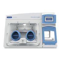
Baker Ruskinn Concept-M User Manual (55 pages)
Anaerobic and Microaerophilic Workstation
Brand:
Baker Ruskinn
| Category:
Laboratory Equipment
| Size: 2 MB
Table of Contents
Table of Contents
2
Table of Figures
4
Introduction
6
Safety Instructions
7
Regulatory Compliance
8
European Region
8
North American Region
9
Precautions
9
Symbols
10
Table 1: List of Symbols
10
Transport and Storage
11
Location and Handling of the Concept Workstation
11
Environmental Operating Conditions
11
Service Requirements
12
Electrical Supply Requirements
12
Figure 1: Concept Rear Connections
12
Table 2: Electrical Service Requirements
12
Gas Supply Requirements
13
Figure 2: Gas Connection Graphic
13
Table 3: Fuse Ratings
13
Table 4: Standard Gases
13
Table 5: Additional Gases for Specific Operating Modes
13
Concept Overview
14
Front View
14
Figure 3: Standard Concept Workstation with SPES Option
14
Figure 4: Large Concept Workstation
14
Front Interior Views
15
Figure 5: Right Side Internal View
15
Figure 6: Left Side Internal View
15
Left Side View
16
Figure 7: Left Side End Panel with Ultrasonic Humidity Option
16
Right Side View
17
Figure 8: Right Side End Panel
17
Rear View
18
Figure 9: Rear End Panel and Supply Connections
18
Figure 10: Gas and Electrical Connections
18
Using the Workstation
19
Using the Interlock
19
Interlock Overview
19
Operating the Interlock Outer Door
19
Icon 1: Interlock Outer Door
19
Operating the Interlock Inner Door
20
Transferring Material into the Workstation Chamber Via the Interlock
20
Screen 1: Interlock Purge Options
21
Removing Material from the Workstation Chamber Via the Interlock
22
Hand Access to the Main Chamber
23
Figure 11: Ezee -Sleeves
23
Vacuum Operation
24
Figure 12: Compressed Ezee-Sleeve for Entry
24
Figure 13: Arm Inserted into Ezee-Sleeve (Shown with and Without Ezee-Sleeve)
24
Figure 14: Foot Pedals for Right and Left Glove Ports
25
Figure 15: Ezee-Sleeve before Vacuum
25
Figure 16: Ezee-Sleeve after Vacuum
25
Workstation Entry
26
Figure 17: Glove Port Cap
26
Figure 18: Glove Port Cap Stowage and Locator
26
Figure 19: Glove Port Cap Storage Location Inside Workstation
27
Workstation Exit
28
Figure 20: Glove Port Cap
28
Figure 21: Glove Port Locator
28
Humidity Control
29
Figure 22: Aquasorb Sachets - Empty and Charged
29
Figure 23: Aquasorb Sachet in Workstation
29
Figure 24: Condensate Plate
30
Figure 25: Condensate Output and Tray
30
Screens
31
Main Screen
31
Initial Settings Screen
32
Screen 4: Initial Settings Screen with Ultrasonic Humidity Option
32
Screen 5: Oxygen Level Set-Point Pop-Up
32
Table 6: Settings Screen Column Functions
32
Screen 6: 0% Oxygen Settings Screen with Aquasorb Humidity Option
33
Environment Control
34
Screen 7: Environment Control Overview
34
Screen 8: Exit Gas Control Warning
34
Data Log
35
Screen 9: Trend Log
35
Utilities
36
Screen 10: Utilities Menu
36
Icon 2: Internal Lights Control
36
Oxygen Sensor Calibration
37
Screen 11: Oxygen Sensor Calibration
37
Help / Settings
38
Screen 12: Help / Settings Menu
38
Warnings
39
Screen 13: Temperature Alarm Screen
39
Screen 14: USB Memory Warning Screen
40
Screen 15: Gas MIX Time Limit Warning Screen
41
Screen 16: Input Gas Pressure Alarm
42
Table 7: Audible Alarm Sounds
42
Usb Trend Log
43
Table 8: Trend Log Data Fields
43
Cleaning and Service Requirements
44
Service and Cleaning Overview
44
Table 8: Cleaning and Service Details
44
Cleaning Procedure - During and after each Use
45
Cleaning Procedure - Deep Clean with Front Screens Removed
46
Figure 26: Front Screen Pneumatic Connector Disconnection
46
Icon 3: Front Screen Release
46
Year Service
49
Figure 27: Ceiling Panel Thumb Screws
49
Figure 28: Ceiling Panel Handle and Grab Catch
49
Figure 29: Large Detox Sachet
50
Figure 30: Large Catalyst Sachets
50
Figure 31: Gloveport Sleeves
50
Troubleshooting
51
The Workstation will Not Switch on
51
The Circuit Breaker Trips
51
Low Gas Pressure
51
Excessive Gas Usage
52
Internal Equipment Not Powering up
52
The Workstation Is Only Partially Operational
52
Warranty Information
53
Disposal Information
54
Contact Details
55
Advertisement
Advertisement
Related Products
Baker Ruskinn Bugbox UM-016
Baker Ruskinn OxyGenie
Baker Ruskinn Sci-tive SI-046
Baker Ruskinn Categories
Laboratory Equipment
More Baker Ruskinn Manuals
Login
Sign In
OR
Sign in with Facebook
Sign in with Google
Upload manual
Upload from disk
Upload from URL