Table of Contents
Advertisement
Available languages
Available languages
Advertisement
Chapters
Table of Contents

Related Manuals for VGE Blue-Lagoon BL530


Summary of Contents for VGE Blue-Lagoon BL530
- Page 1 BL530 PH/RX DOSAGE SYSTEM UV-C and Pool equipment TECHNICAL MANUAL MEMBER OF:...
-
Page 2: Table Of Contents
BL530 PH/RX DOSAGE SYSTEM TABLE OF CONTENTS CONTENT BOX INTRODUCTION INSTALLATION TECHNICAL SPECIFICATIONS FUNCTIONAL DESCRIPTION OF THE SYSTEM HYDRAULIC CONNECTIONS Suction Line Injection Line ELECTRICAL CONNECTIONS Level Control Flow Protection INTERNAL CONNECTIONS (FOR INSTALLERS ONLY) START-UP DISPLAY OPERATION OF THE ELECTRONIC UNIT Standard Configuration Advanced Configuration List of Configuration Parameters... - Page 3 UV-C and Pool equipment UV-C and Pool equipment WARNINGS This manual is dedicated to the technical personnel responsible of the installation, management and maintenance of the plants. The manufacturer assumes no responsibility for damages or malfunctions occurring after intervention by non-authorized personnel, or not compliant with the prescribed instructions.
-
Page 4: Content Box
BL530 PH/RX DOSAGE SYSTEM CONTENT BOX The BL530 unit is supplied already wired internally, and complete with: 1. BH08014 pH electrode with 2.5 m cable and BNC connector. 2. BH08015 redox electrode with platinum sensor, 2.5 m cable and BNC connector. 3. -
Page 5: Technical Specifications
UV-C and Pool equipment TECHNICAL SPECIFICATIONS pH/RX Inputs Available on BNC connectors, input impedance > 10^12 Ω. Measure Ranges 0.00 to 14.00 pH, 0 to 1000 mV (redox). Precision Deviations less than 1% of the full scale (when properly calibrated). Precision Repeatability Better than 0.2% of the full scale. -
Page 6: Functional Description Of The System
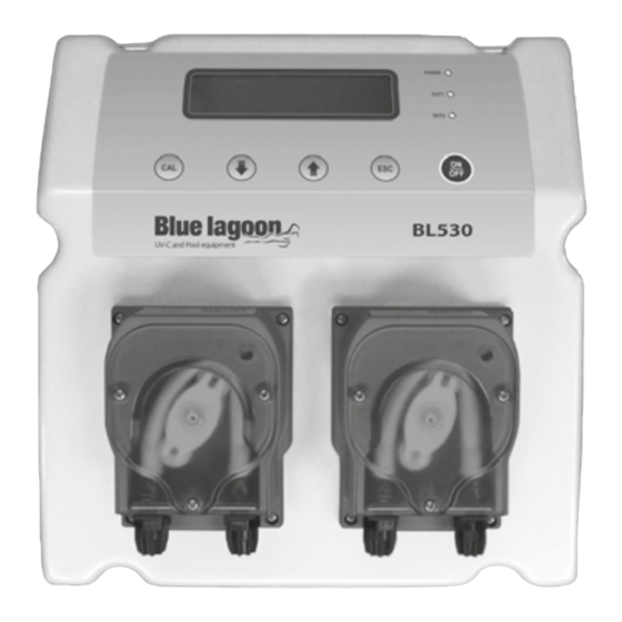
BL530 PH/RX DOSAGE SYSTEM FUNCTIONAL DESCRIPTION OF THE SYSTEM Front view Bottom view: connections • POWER Power cable (pre-wired). • BNC connector for pH electrode. • BNC connector for redox electrode. • LEV1 Connector for level • Control panel with large display and sensor of tank 1 (acid). -
Page 7: Hydraulic Connections
UV-C and Pool equipment HYDRAULIC CONNECTIONS Check that the suction line does not exceed the maximum height of 1.5 m from the tank bottom. Unscrew the pipe-wrench nut and remove the two protective caps from fittings (in the case a pump head needs to be removed, it is recommended to reuse the protective caps, to prevent any leakage from the pump body). -
Page 8: Injection Line
BL530 PH/RX DOSAGE SYSTEM Injection Line (also see drawing on the previous page) 1. Unscrew the fixing nut of the connector located on the bottom right side of the pump head and marked in the figure with an outgoing arrow. 2. -
Page 9: Flow Protection
UV-C and Pool equipment Flow protection: The system is supplied already configured for disabling the dosage in case of lack of water flow. The control is made through a contact to be connected to pins 3 and of the FLOW connector (see Figure). -
Page 10: Start-Up
BL530 PH/RX DOSAGE SYSTEM START-UP At start-up the microcontroller displays for a couple of seconds information about the firmware (type / version), then shows the two measures flashing for all the start-up delay time (if set) and then starts operating accordingly with the configured working mode. DISPLAY During normal operations, the display shows the two measured values on the top line, while the bottom row displays the status of the two pumps. -
Page 11: Operation Of The Electronic Unit
UV-C and Pool equipment OPERATION OF THE ELECTRONIC UNIT To access the configuration, calibration and manual mode menus, press the CAL button. The display will show the following available options: • Standard Configuration. • Advanced Configuration. • Calibration IN1 (input 1) pH. •... -
Page 12: List Of Configuration Parameters
BL530 PH/RX DOSAGE SYSTEM List of Configuration Parameters In this section are listed all the configuration parameters. It is recommended to fill the last column with the values set for your application. Default Description Min. Value Max. Value Value Value Functioning Type Pump 1 ON-OFF / Proportional... - Page 13 UV-C and Pool equipment Warning! The complete list of parameters can be accessed only from the “Advanced Configuration” menu, while the “Standard Configuration” mode allows to modify only the parameters that are not protected by password (highlighted in bold in the table above). PARAMETER 01 FUNCTIONING TYPE OF THE PUMP 1 This parameter allows to set the functioning type of pump 1, typically used for the pH control.
- Page 14 BL530 PH/RX DOSAGE SYSTEM PARAMETER 09 DOSAGE DIRECTION OF PUMP 2 See parameter P04, but referred to redox measurements and dosing directions “Chlorination / De- chlorination”. PARAMETER 10 TIME BASE FOR PUMP 2 See parameter P05, but referred to the pump 2. PARAMETER 11 DOSAGE ALARM OF PUMP 1 This parameter allows to generate an alarm when the measurement does not return to the setpoint value within a set time interval, from 0 (function disabled) to 240 minutes.
- Page 15 UV-C and Pool equipment PARAMETER 16 PASSWORD This parameter allows to enter a password (numeric value within 1 and 255) to protect the system from unauthorized access. Once set and confirmed, the password will be requested to access the menus “Advanced configuration” and “Manual mode”. The instrument is supplied with no password set (P16=0).
-
Page 16: Electrochemical Calibration
BL530 PH/RX DOSAGE SYSTEM Electrochemical Calibration pH Calibration > > 1. Rinse the pH electrode with distilled water, then immerse it in the pH 7.01 pH buffer solution. 2. Press the CAL key to enter the menu mode and use the / keys to select the option “IN1 CALIBRATION”. -
Page 17: Manual Mode
UV-C and Pool equipment close to neutrality, the procedure will fail. During normal operation, it is possible to view the offset (pressing ) and gain (pressing ) • values, to check the electrode status. The ideal values are an offset close to zero and a gain close to 1.000. -
Page 18: Control Examples
BL530 PH/RX DOSAGE SYSTEM > > Warning! In manual mode only one pump at a time can be activated. CONTROL EXAMPLES Typical application in swimming pool control: acidification when pH exceeds the pH value of 7.30. Refer to the “List of configuration parameters” and set: •... -
Page 19: Maintenance
UV-C and Pool equipment can be generated by a dead or broken electrode, or by a damaged or disconnected cable; check the system and restore correct measurement conditions. AL.1 / AL.2 Dosing time alarm for pump 1 or 2: measurement is outside the set-point for a time longer than the set limit, due to an insufficient dosage or a wrong configuration of the alarm time (see parameters P11 and P12);... -
Page 20: Maintenance
BL530 PH/RX DOSAGE SYSTEM Extraordinary maintenance – Replacing the peristaltic tube: Unscrew the two front screws and remove the transparent cover. To remove the old tube, first release the left connector and then turn the roller-holder as shown by the arrow in the figure, to free the tube up to the right connector. -
Page 21: Accessories And Spare Parts
UV-C and Pool equipment ACCESSORIES AND SPARE PARTS Item Nr. Image Description BH08014 pH electrode , 2.5 m cable and BNC connector. BH08015 Redox electrode , 2.5 m cable and BNC connector. SP0001 Electrode-holder 1/2" PVC. SP0002 Electrode storage solution 500ml. SP0003 Injection valve 1/2". - Page 22 BL530 PH/RX DOSAGE SYSTEM Item Nr. Image Description SP0009 Electric motor 230V 1,8 L/h for BL220. SP0010 Tube rollers for BL530, BL210, BL212. SP0011 Tube rollers for BL220. SP0012 Suction lance for 50 ltr tank, BL530, BL220. SP0013 Saddle clamp DN50. Suction and delivery tubes 2 x 2 mtr, SP0014 injection valve and foot filter.
- Page 23 UV-C and Pool equipment Item Nr. Image Description SP0018 Transparent front cover peristaltic pump, for BL220. SP0019 Santoprene internal tube for peristaltic pumps, for BL220. Santoprene internal tube peristaltic SP0020 pumps, for BL530, BL210, BL212. SP0021 Level sensor with 2 m cable and connector. SP0022 Cleaning and storage kit for pH and redox electrodes.
- Page 24 BL530 PH/RX DOSIERSYSTEM INHALT VERPACKUNGSINHALT EINFÜHRUNG INSTALLATION TECHNISCHE DATEN FUNKTIONSBESCHREIBUNG DES SYSTEMS HYDRAULIKANSCHLÜSSE Ansaugleitung Injektionsleitung ELEKTRISCHE ANSCHLÜSSE Füllstandskontrolle 30 - 31 Durchflusssicherheit INTERNE ANSCHLÜSSE (NUR FÜR INSTALLATEURE) INBETRIEBNAHME DISPLAY BEDIENUNG DER ELEKTRONISCHE EINHEIT Standard Configuration Advanced Configuration 33 - 34 Liste der Konfigurationsparameter 34 - 37 Elektrochemische Kalibrierung...
- Page 25 UV-C and Pool equipment UV-C and Pool equipment WARNUNGEN Dieses Handbuch richtet sich an das für die Installation, Verwaltung und Instandhaltung der Anlagen zuständige technische Personal. Der Hersteller haftet nicht für Schäden oder Fehlfunktionen, die nach einem Eingriff durch unbefugtes Personal oder den vorgeschriebenen Anweisungen entgegenstehenden Maßnahmen auftreten.
-
Page 26: Verpackungsinhalt
BL530 PH/RX DOSIERSYSTEM VERPACKUNGSINHALT Bei Auslieferung ist die Steuerung BL530 vollständig verdrahtet und versehen mit: 1. BH08014 pH-Elektrode mit Kabel (2,5 m) und BNC-Steckverbinder. 2. BH08015 Redox-Elektrode mit Platinsensor (2,5 m) und BNC-Steckverbinder. 3. 2 PVC-Elektrodenhalter mit DN50-Klemme zur direkten Inline-Installation von Elektroden. 4. -
Page 27: Technische Daten
UV-C and Pool equipment TECHNISCHE DATEN pH/RX-Eingänge An BNC-Anschlüssen, Eingangswiderstand > 10^12 Ω. Messbereiche 0,00 bis 14,00 pH, 0 bis 1000 mV (Redox), Genauigkeit Abweichungen von weniger als 1 % der vollen Skala (wenn korrektkalibriert). Wiederholgenauigkeit Besser als 0,2% des Maximalwerts. Konfiguration 2 Konfigurationsebenen ("Standard"... -
Page 28: Funktionsbeschreibung Des Systems
BL530 PH/RX DOSIERSYSTEM FUNKTIONSBESCHREIBUNG DES SYSTEMS Vorderseite Unterseite: Anschlüsse • POWER Netzkabel (vorverdrahtet). • pH BNC-Steckverbinder für pH-Elektrode. • RX BNC-Steckverbinder für Redox-Elektrode. • LEV1 Anschluss für Pegelsensor • Bedienfeld mit großer Anzeige und Tasten von Behälter 1 (Säure). (siehe Beschreibung nächste Seite). •... -
Page 29: Hydraulikanschlüsse
UV-C and Pool equipment HYDRAULIKANSCHLÜSSE Überprüfen Sie, dass die Ansaugleitung die maximale Höhe von 1,5 m ab Behälterboden nicht übersteigt. Lösen Sie den Schlauchschlüssel und entfernen Sie die beiden Schutzkappen von den Verschraubungen (falls ein Pumpengehäuse entfernt werden muss, sollten die Schutzkappen benutzt werden, um eine Undichtigkeit des Pumpenkörpers zu vermeiden). -
Page 30: Injektionsleitung
BL530 PH/RX DOSIERSYSTEM Injektionsleitung (siehe Zeichnung vorhergehende Seite) 1. Lösen Sie die Befestigungsmutter des Anschlusses unten rechts am Pumpenkopf (in der Abbildung mit einem Eingangspfeil markiert). 2. Schneiden Sie den weißen halbstarren Polyethylen Schlauch auf die notwendige länge zurecht. 3. Führen Sie die Befestigungsmutter und der Schlauchtülle auf den Schlauch. 4. -
Page 31: Durchflusssicherheit
UV-C and Pool equipment Der Alarmzustand wird mit einigen Sekunden Verzögerung nach dem Feststellen des niedrigen Füllstands erzeugt, um Fehlalarme aufgrund extremer Bedingungen (z. B. Wasserschwankungen) zu vermeiden. Es gibt zwei Eingänge für Füllstandsensoren, jeweils einen pro Pumpe/Behälter. Durchflusssicherheit Das System ist bei Auslieferung so konfiguriert, dass es die Dosierung bei einem zu geringen Wasserdurchfluss deaktiviert. -
Page 32: Inbetriebnahme
BL530 PH/RX DOSIERSYSTEM INBETRIEBNAHME Beim Einschalten zeigt der Mikrocontroller einige Sekunden lang Informationen zur Firmware (Typ/Version); dann blinken die beiden Messwerte für die Dauer der Einschaltverzögerung (sofern eingestellt). Anschließend startet das Gerät entsprechend dem konfigurierten Betriebsmodus. DISPLAY Im normalen Betrieb zeigt das Display in der oberen Zeile die beiden Messwerte und in der unteren Zeile den Status der beiden Pumpen. -
Page 33: Bedienung Der Elektronische Einheit
UV-C and Pool equipment BEDIENUNG DER ELEKTRONISCHE EINHEIT Um die Menüs „Configuration“, „Calibration“ und „Manual mode“ aufzurufen, drücken Sie die Taste CAL. Das Display zeigt daraufhin die folgenden verfügbaren Optionen: • Standard Configuration • Advanced Configuration • Calibration IN1 (input 1) pH •... -
Page 34: Liste Der Konfigurationsparameter
BL530 PH/RX DOSIERSYSTEM 2. Gehen Sie nun mit den Tasten und die Liste der verfügbaren Parameter durch. 3. Um die angezeigten Parameter zu ändern, drücken Sie auf CAL, um abzubrechen, auf ESC. > > Liste der Konfigurationsparameter In diesem Abschnitt sind alle Konfigurationsparameter aufgeführt. In der letzten Spalte sollten Sie die Werte eintragen, die Sie für Ihre Anwendung eingestellt haben. - Page 35 UV-C and Pool equipment Alarmfunktion Relais NO/ Relais NC Relais NO Flussfunktion Eingang NO/ Eingang NC Eingang NO pH-Balance 0 Min. 240 Min. 0 Min. Warnung! Die vollständige Liste der Parameter kann nur über das Menü „Advanced Configuration“ aufgerufen werden. Im Modus „Standard Configuration“ können nur die Parameter konfiguriert werden, die nicht passwortgeschützt (in der Tabelle oben fett markiert) sind.
- Page 36 BL530 PH/RX DOSIERSYSTEM PARAMETER 08 HYSTERESE PUMPE 2 Siehe Parameter P03, aber bezogen auf Redox-Messungen. PARAMETER 09 DOSIERBEFEHL PUMPE 2 Siehe Parameter P04, aber bezogen auf Redox-Messungen und Dosieranweisung „Chlorination / De-chlorination“. PARAMETER 10 ZEITBASIS PUMPE 2 Siehe Parameter P05, aber bezogen auf Pumpe 2. PARAMETER 11 DOSIERBEFEHL PUMPE 1 Mit diesem Parameter kann Alarm ausgelöst werden, falls die Messung nicht innerhalb eines festgelegten Zeitintervalls zwischen 0 (Funktion deaktiviert) und 240 Minuten zum Sollwert...
- Page 37 UV-C and Pool equipment PARAMETER 16 PASSWORT Mit diesem Parameter können Sie ein Passwort (ein numerischer Wert zwischen 1 und 255) eingeben, um das System vor einem unbefugten Zugriff zu schützen. Nachdem das Passwort eingegeben und betätigt wurde, wird es für den Zugriff die Menüs „Advanced Configuration“ und „Manual Mode“...
-
Page 38: Elektrochemische Kalibrierung
BL530 PH/RX DOSIERSYSTEM Elektrochemische Kalibrierung pH-Kalibrierung > > 1. Spülen Sie die pH-Elektrode mit destilliertem Wasser und tauchen Sie sie dann in die pH 7.01-Pufferlösung. 2. Drücken Sie die Taste CAL, um den Menümodus aufzurufen und wählen Sie mit den Tasten ... -
Page 39: Manueller Modus
UV-C and Pool equipment die Kalibrierung automatisch ignoriert. Desgleichen ist es nicht möglich, den Gain mit einer Pufferlösung bei einem nahezu neutralen pH-Wert zu kalibrieren. • Im Normalbetrieb kann man den Offset-Wert ( drücken) und den Gain-Wert ( drücken) aufrufen, um den Elektrodenstatus zu prüfen. Die idealen Werte sind ein Offset nahe Null und ein Gain nahe 1.000. -
Page 40: Kontrollbeispiele
BL530 PH/RX DOSIERSYSTEM 3. Verfahren Sie genauso für Pumpe 2. 4. Mit ESC können Sie den manuellen Modus jederzeit wieder beenden. > > Warnung! Im manuellen Modus kann jeweils immer nur eine Pumpe aktiviert werden. KONTROLLBEISPIELE Typische Anwendung zur Schwimmbeckenkontrolle: Ansäuerung, wenn der pH-Wert 7.30 überschritten wird. -
Page 41: Instandhaltung
UV-C and Pool equipment FLOW Der Durchflusssensor hat eine Unregelmäßigkeit festgestellt, die auf einen zu geringen Druck im Hydraulikkreis oder eine falsche Justierung des Durchflusssensors im Elektrodenhalter hinweisen könnte: korrekten Durchfluss wiederherstellen oder den Sensor justieren. STOP Diese Meldung bedeutet, dass die Pumpen durch Betätigen der Taste ON/OFF manuell deaktiviert wurden. - Page 42 BL530 PH/RX DOSIERSYSTEM • Wiederholen Sie den Vorgang mit sauberem Wasser. Schließen Sie Pumpe nach dem Reinigen wieder an die Anlage an und setzen Sie den normalen Betrieb fort. Außerplanmäßige Wartung – Austausch des Peristaltikschlauchs: Lösen Sie die beiden vorderen Schrauben und entfernen Sie die transparente Abdeckung.
-
Page 43: Zubehör Und Ersatzteile
UV-C and Pool equipment ZUBEHÖR UND ERSATZTEILE Artnr. Abbildung Umschreibung pH-Elektrode mit Kunststoffkörper, 2,5 m Kabel BH08014 und BNC-Stecker. Redox Elektrode mit Kunststoffkörper Pt-Sensor; 2,5 m BH08015 Kabel mit BNC-Stecker. SP0001 Elektrodenhalter 1/2" PVC. SP0002 Elektroden Aufbewahrungslösung 500ml. SP0003 Einspritzventil 1/2". SP0004 Saugventil PP / LIP Viton. - Page 44 BL530 PH/RX DOSIERSYSTEM Artnr. Abbildung Umschreibung SP0009 Elektromotor 230V 1,8 l/h für BL220. SP0010 Schlauchrollen, für BL530, BL210, BL212. SP0011 Schlauchrollen für BL220. SP0012 Sauglanze für 50-Liter-Tank, BL530, BL220. SP0013 Sattelklemme DN50. Saug- und Druckrohre 2x2m, Injektionsventil und SP0014 Fußfilter. Ersatz Kopf für peristaltische Pumpe mit Einsätzen für SP0015 BL220.
- Page 45 UV-C and Pool equipment Artnr. Abbildung Umschreibung Transparenter Frontabdeckung für peristaltische SP0018 Pumpen, für BL220. SP0019 Santoprene Innenrohr für Schlauchpumpen, für BL220. Santoprene Innenrohr für Schlauchpumpen, für BL530, SP0020 BL210, BL212. SP0021 Niveausensor mit 2m Kabel und Stecker. Reinigungs- und Aufbewahrungsset für pH- und Redox SP0022 Elektroden.
- Page 46 BL530 PH/RX DOSEERSYSTEEM INHOUDSOPGAVE INHOUD VERPAKKING INLEIDING INSTALLATIE TECHNISCHE SPECIFICATIES FUNCTIEBESCHRIJVING VAN HET SYSTEEM HYDRAULISCHEAANSLUITINGEN Zuigleiding Injectieleiding ELEKTRISCHE AANSLUITINGEN Niveauregeling 52 - 53 Stroomregeling INTERNE VERBINDINGEN (ALLEEN VOOR INSTALLATEURS) OPSTARTEN DISPLAY WERKING VAN DE ELEKTRONISCHE UNIT Standaardconfiguratie Geavanceerde Configuratie 55 - 56 Lijst van Configuratieparameters 56 - 59 Elektrochemische kalibratie...
- Page 47 UV-C and Pool equipment UV-C and Pool equipment WAARSCHUWINGEN Deze handleiding is bedoeld voor installateurs die verantwoordelijk zijn voor de installatie, het beheer en onderhoud van de installaties. De fabrikant neemt geen verantwoordelijkheid op zich voor schade of storingen die zich voordoen na ingrepen van niet-bevoegd personeel, of na ingrepen die niet voldoen aan de voorgeschreven instructies.
-
Page 48: Inhoud Verpakking
BL530 PH/RX DOSEERSYSTEEM INHOUD VERPAKKING De BL530 unit is bij levering reeds intern bedraad en wordt compleet geleverd met: 1. BH08014 pH-elektrode met 2,5 m kabel en BNC connector. 2. BH08015 redoxelektrode met platina sensor, 2,5 m kabel en BNC connector. 3. -
Page 49: Technische Specificaties
UV-C and Pool equipment TECHNISCHE SPECIFICATIES pH-/RX-ingangen Beschikbaar op de BNC connectoren, ingangsimpedantie> 10 ^ 12 Ω. Meetbereiken pH 00 tot 14,00, redox 0-1000 mV. Nauwkeurigheid Afwijkingen minder dan 1% van de volledige schaal (mits juist gekalibreerd). Herhalingsnauwkeurigheid Hoger dan 0,2% van de volledige schaal. Configuratie Twee configuratieniveaus (standaard en geavanceerd). -
Page 50: Functiebeschrijving Van Het Systeem
BL530 PH/RX DOSEERSYSTEEM FUNCTIEBESCHRIJVING VAN HET SYSTEEM Vooraanzicht Onderaanzicht: verbindingen • POWER Stroomkabel (voorbedraad). • BNC-connector voor pH elektrode. • BNC connector voor redox-elektrode. • Bedieningspaneel met een groot display • LEV1 Connector voor niveausensor en toetsenbord (zie beschrijving op de van tank 1 (zuur). -
Page 51: Hydraulischeaansluitingen
UV-C and Pool equipment HYDRAULISCHE AANSLUITINGEN Controleer of de zuigleiding de maximale hoogte van 1,5 m vanaf de bodem van de tank niet overschrijdt. Draai de leidingmoer los en verwijder de twee beschermkapjes van de aansluiting (in het geval dat een pompkop moet worden weggehaald is het raadzaam om de beschermkapjes te hergebruiken om lekkage van het pomphuis te voorkomen). -
Page 52: Injectieleiding
BL530 PH/RX DOSEERSYSTEEM Injectieleiding (zie ook de tekening op de vorige pagina) 1. Draai de bevestigingsmoer van de in de figuur met een uitgaande pijl aangegeven connector aan de rechteronderkant van de pompkop los. 2. Snijd de witte, semi-buigzame polyethyleen slang door op de juiste lengte. 3. -
Page 53: Stroomregeling
UV-C and Pool equipment De alarmtoestand wordt gegenereerd met een vertraging van enkele seconden ten opzichte van de detectie van een laag niveau, om fouten ten gevolge van extreme situaties (zoals waterschommelingen) te voorkomen. Er zijn twee ingangen voor de niveausensoren beschikbaar, één voor elke pomp/tank. -
Page 54: Opstarten
BL530 PH/RX DOSEERSYSTEEM OPSTARTEN Bij het opstarten geeft de microprocessor enkele seconden informatie weer over de firmware (type / versie), toont vervolgens de twee metingen die knipperen gedurende de opstartvertragingstijd (indien ingesteld) en begint vervolgens in de geconfigureerde bedrijfsmodus te werken. DISPLAY Tijdens de normale werking, toont het display de twee gemeten waarden op de bovenste regel, terwijl op de onderste regel de status van de twee pompen wordt weergegeven. -
Page 55: Werking Van De Elektronische Unit
UV-C and Pool equipment WERKING VAN DE ELEKTRONISCHE UNIT Om toegang te krijgen tot de menu's van configuratie, kalibratie en handmatige modus drukt u op de CAL-toets. Op het display verschijnen de volgende beschikbare opties: • Standaard Configuratie. • Geavanceerde Configuratie. •... -
Page 56: Lijst Van Configuratieparameters
BL530 PH/RX DOSEERSYSTEEM 2. Gebruik nu de toetsen en om door de lijst van beschikbare parameters te scrollen. 3. Druk op CAL om de weergegeven parameter te wijzigen, druk op ESC om de modus te verlaten. > > Lijst van Configuratieparameters In dit hoofdstuk ziet u al onze configuratieparameters. - Page 57 UV-C and Pool equipment Wachtwoord Alarmfunctionering Relais NO / Relais NG Relais NO Stroomfunctionering Ingang NO / Ingang NG Input NO pH Equilibrium 0 min. 240 min. 0 min. Waarschuwing! De volledige lijst parameters kan alleen worden geopend via het menu "Geavanceerde Configuratie", terwijl in de modus "Standaardconfiguratie"...
- Page 58 BL530 PH/RX DOSEERSYSTEEM PARAMETER 07 INSTELPUNT POMP 2 Zie parameter P02, maar verwijzend naar redox-metingen. PARAMETER 08 HYSTERESIS POMP 2 Zie parameter P03, maar verwijzend naar redox-metingen. PARAMETER 09 DOSERINGSRICHTING VAN POMP 2 Zie parameter P04, maar verwijzend naar redox-metingen en doseerrichtingen “Chlorering / De-chlorering”.
- Page 59 UV-C and Pool equipment PARAMETER 15 HERSTEL DE STANDAARDINSTELLINGEN Deze functie biedt de mogelijkheid om terug te keren naar de fabrieksinstellingen wanneer u onjuiste of ongewenste instellingen wenst te verwijderen. Wanneer deze optie eenmaal bevestigd is, zullen alle voorkeursinstellingen verloren gaan. Om deze functie in te schakelen, voert u de waarde "12"...
-
Page 60: Elektrochemische Kalibratie
BL530 PH/RX DOSEERSYSTEEM Elektrochemische kalibratie pH kalibratie > > 1. Spoel de pH elektrode af met gedestilleerd water en dompel hem dan onder in de bufferoplossing met een pH van 7,01. 2. Druk op de CAL-toets om het menu te openen en gebruik de / toetsen om de optie “IN1 KALIBRATIE”... -
Page 61: Handmatige Modus
UV-C and Pool equipment de kalibratie automatisch genegeerd. Indien u probeert om de gain te kalibreren met een bufferoplossing met een pH die te dicht bij neutraal is, zal de procedure evenzo mislukken. • Tijdens normaal bedrijf is het mogelijk de waarde van offset te zien (door te drukken op ) en de waarde van gain (door te drukken op ) om de status van de elektrode te controleren. -
Page 62: Regelvoorbeelden
BL530 PH/RX DOSEERSYSTEEM 2. Druk nogmaals op CAL om te bevestigen. 3. Ga op dezelfde manier te werk voor pomp 2. 4. Druk op elk gewenst moment op ESC om de handmatige modus te verlaten. > > Waarschuwing! In de handmatige modus kan slechts één pomp tegelijk worden geactiveerd. -
Page 63: Onderhoud
UV-C and Pool equipment FLOW De flowsensor detecteerde een afwijking die te wijten kan zijn aan een lage druk in het hydraulische circuit of een verkeerde afstelling van de flowsensor in de elektrode-houder; herstel de flow of pas de sensor aan. STOP Dit bericht geeft aan dat de pompen handmatig zijn gedeactiveerd door op de ON/OFF-toets te drukken. - Page 64 BL530 PH/RX DOSEERSYSTEEM Buitengewoon onderhoud - de peristaltische buis vervangen: Draai de twee schroeven aan de voorkant los en verwijder de transparante afdekking. Verwijdering van de oude slang: maak eerst de linkerconnector los en draai de roller-houder, zoals aangegeven door de pijl in de figuur om de slang tot aan de rechterconnector los te halen.
-
Page 65: Accessoires En Reserveonderdelen
UV-C and Pool equipment ACCESSOIRES EN RESERVEONDERDELEN Artnr. Afbeelding Omschrijving BH08014 pH electrode, 2,5 mtr kabel + BNC Connector. BH08015 Rodex Electrode, 2,5 mtr kabel + BNC Connector. SP0001 Elektrodehouder 1/2" PVC. SP0002 Elektrode bewaarvloeistof 500 ml. SP0003 Injectieventiel 1/2". SP0004 Aanzuigventiel PP/LIP Viton. - Page 66 BL530 PH/RX DOSEERSYSTEEM Artnr. Afbeelding Omschrijving SP0009 Electromotor 230V, 1,8 L/uur t.b.v. BL220. SP0010 Slang rollers t.b.v. BL530, BL210, BL212. SP0011 Slang rollers t.b.v. BL220. SP0012 Aanzuiglans t.b.v. 50 ltr. Tank t.b.v. BL530, BL220. SP0013 Aanboorzadel DN50. zuig- en persslangenset 2x2 mtr, incl. injectieventiel en SP0014 voetfilter.
- Page 67 UV-C and Pool equipment Artnr. Afbeelding Omschrijving SP0018 Deksel t.b.v. peristaltische pomp transp. T.b.v. BL220. SP0019 Santopreen slang t.b.v. peristaltische pomp t.b.v. BL220. Santopreen slang t.b.v. peristaltische pomp t.b.v. BL530, SP0020 BL210, BL212. SP0021 Niveausensor met 2 mtr kabel en connector. SP0022 Reinigings en opbergkit voor pH en Redox electrode.
- Page 68 VGE International B.V. Ekkersrijt Son & Breugel The Netherlands Tel. +31(0) 499 461 099 Fax +31(0) 499 494 229 info@vgebv.nl www.vgebv.com Made in the www.bluelagoonuvc.com Netherlands...
Need help?
Do you have a question about the Blue-Lagoon BL530 and is the answer not in the manual?
Questions and answers