
Related Manuals for touch bionics i-limb ultra revolution


Summary of Contents for touch bionics i-limb ultra revolution
- Page 1 i-limb ultra revolution Clinician Manual Part number: MA01140: Issue No. 4, December 2014...
- Page 2 This document provides instruction for prosthetists in the fitting and servicing of the i-limb ultra revolution and should be read in full prior to fitting. It is highly recommended that the use of this manual is made in conjunction with instruction from a clinician experienced in upper limb and myoelectric prostheses.
-
Page 3: Table Of Contents
Table of Contents 1. i-limb ultra revolution Product Description Intended Use Prosthesis Overview 2. Socket Control Sites Socket Fabrication Charge Port Placement Assembly Battery Options Battery Configuration Battery Installation i-limb Power Pack Battery Charging 3. Wrist Wrist Connection Options Quick Wrist Disconnect (QWD) -
Page 4: I-Limb Ultra Revolution
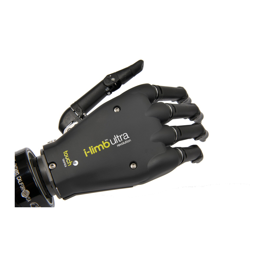
(auto-grasp) and the wide range of automated grip patterns lead to broad functionality. 1.2 Intended Use The i-limb ultra revolution is intended to be used by patients with upper limb loss or deficiency 1.3 Prosthesis Overview The hand serial number is positioned proximal to the base of the thumb on the connection plate. - Page 5 Motorized Digit Knuckle Palmar Fairing Motorized Thumb On / Off Switch 5 of 33 Part number: MA01140: Issue No. 4, December 2014...
-
Page 6: Socket
2.0 Socket Figure 1. Electrode Options 2.1 Control Sites One option for control of the i-limb ultra revolution is electrodes. There are two electrode options available for use with the i-limb ultra revolution, compact electrodes (fig. 1) or remote electrodes (fig. - Page 7 2.2 Socket Fabrication Figure 4. Coaxial Plug While fabricating the socket for the i-limb ultra revolution, special considerations will need to be given to: 1. Battery placement, size and configuration 2. Electrode position or other control method 3. Charge port placement 4.
- Page 8 2.3 Charge Port Placement Assembly It is important to provide sufficient space for the charge port between the inner and outer sockets. The charge port should be positioned so that it is unaffected by forces running through the socket to prevent damage. Create a drill hole of 8.0mm through the inner surface of the prosthetic frame.
- Page 9 2.4 Battery Options Two battery options are available for the i-limb ultra revolution, both of which have been specifically designed to meet the power requirements of the hand. Battery selection should be based on available space within the socket fabrication, shape of the residual limb and the expected level of use.
- Page 10 The battery with DC connector and battery with switch block connector are shown. Only Touch Bionics batteries are approved for use with the i-limb ultra revolution. Use of alternative batteries will invalidate the warranty and compromise general safety of the device.
- Page 11 Battery Placement Use Velcro™ to position the batteries on the pre-prepared flat surfaces to prevent distortion. Battery Placement for a Long Residual Limb Consideration of battery placement is particularly important in longer sockets. The shape of the inner socket must also be considered.
- Page 12 When the switch block is used in combination with a wrist rotator Wiring Schematic for 1300mAh Low Profile the switch block will simultaneously turn off the i-limb ultra Battery with D.C. Socket revolution and the electronic wrist rotator. 2.5mm D.C. Socket Co-axial Bush/Rotator Do not apply excessive force to the charger socket interface during assembly.
- Page 13 2.7 i-limb Power Pack Bottom of socket Top of socket i-limb Power Pack (ordered separately) are for users who want the ability to easily replace batteries. Battery housing is fabricated on top and bottom of socket, allowing for easy access. i-limb Power Pack kit Figure.
- Page 14 If the patient intends to travel outside of their home country, they will need to ensure they have a Touch Bionics charger that will work in the country to which they are traveling. Additional chargers are available from Touch Bionics.
- Page 15 Figure. 17 i-limb Power Pack batteries for i-limb ultra revolution should only be charged using the Touch Bionics battery charger (fig. 17) supplied. Place the batteries in the charger as illustrated. Insert the charger lead from the battery powerpack into the charge port.
-
Page 16: Wrist
Connecting the i-limb ultra revolution using the Ensure the i-limb ultra revolution is switched off. On/Off Switch Align the QWD connection of the i-limb ultra revolution with the connection in the forearm socket. 16 of 33 Part number: MA01140: Issue No. 4, December 2014... - Page 17 Test the connection is fully engaged with a slight rotation. Disconnecting the i-limb ultra revolution using the QWD Ensure the i-limb ultra revolution is switched off. Support the i-limb ultra revolution in the palm of the hand. 17 of 33 Part number: MA01140: Issue No. 4, December 2014...
- Page 18 3.3 Wrist Disarticulation The wrist disarticulation is fabricated directly into the socket frame and then attached to the i-limb ultra revolution by the following steps: Disconnect the Palm Fairing from the i-limb ultra revolution chassis by unscrewing the screw in the palmar surface using a T10 Screwdriver (available for order).
- Page 19 Remove the Wrist Disarticulation and feed the power cable through. Align the slots and slide the Wrist Disarticulation plate onto the WD Lamination Plate at base of the i-limb ultra revolution ensuring it is firmly engaged. Secure the Wrist Disarticulation plate to the WD Lamination Plate using a T10 screw and a T10 Screwdriver.
- Page 20 The magnetic control switch for locking is located on the medial/lateral portion of the wrist. Refer to flexion wrist data sheet for more information on the Touch Bionics website: www. touchbionics.com/downloads/document-library/. Note: When unlocking you must disengage the spring by putting pressure against the i-limb device in the direction the hand was locked.
-
Page 21: Adjustments
2, 3, 5 and 6. Sizes 2 and 3 contain a small motor, while sizes Digit Small Medium 5 and 6 contain a larger motor. The standard digit configuration of the small and medium sized i-limb ultra revolution is outlined Thumb in the table. Index Middle... - Page 22 4.3 Thumb Installation The i-limb ultra revolution is only compatible with a Touch Bionics’ i-limb ultra revolution thumb. To exchange a thumb ensure the correct size has been selected.
- Page 23 Disconnect the palmar fairing using a T10 screwdriver to loosen the palmar T10 screw. Gently move the palmar fairing to the ulnar side to allow access to the exposed T10 screw at the base of the thumb. Using a T10 Screwdriver access the screw from the medial to lateral direction to loosen.
- Page 24 If there is resistance while tightening the screw check for cross threading by removing and re-inserting the screw. Touch Bionics recommends T10 Screwdriver for use with all T10 screws in the i-limb ultra revolution. 24 of 33 Part number: MA01140: Issue No. 4, December 2014...
-
Page 25: Covers
5.1 Cover Options Coverings are an important part of the appearance and durability of upper limb prostheses. The Touch Bionics i-limb products are the first prosthetic hands and fingers to imitate the individual digit articulation of the human hand, and we provide flexible coverings which enable that articulation. -
Page 26: Grip Review
6.0 Grip Review The i-limb ultra revolution has 24 different Quick Grip options available. These Quick Grips can be accessed through biosim-pro and the biosim app. The following features catalogue will review the various available Quick Grips and provide a functional description of each. - Page 27 Additional Grip and Gesture Options Thumb Park Continuous Thumb Park Quick all four fingers remain open and switch off, all four fingers remain open and switch only the thumb will move. off, for 1.5 seconds the thumb will close and then automatically return to an open position.
-
Page 28: Support Information
Always turn off the hand when not in use. Aim to charge the battery each day after use. Replace the battery every 12 months. Ensure i-limb ultra revolution is serviced every 12 months 28 of 33 Part number: MA01140: Issue No. 4, December 2014... - Page 29 Check the electrode cable is not damaged Check the battery cable is not damaged Check that the i-limb ultra revolution is connected correctly to the wrist Contact Touch Bionics Electrode settings may be too low User complains that the...
- Page 30 Do not expose to high temperatures. regulations. Do not expose to flames. Only use the appropriate Touch Bionics charger to charge Touch Do not use or expose to explosive atmospheres. Bionics batteries. Do not disassemble componentry or modify in any way.
-
Page 31: User Information
8.1 User Details Provision of the following information will enable easy identification of your patient’s device, should it be returned to customer service. Please forward to Touch Bionics as per the contact information on the back page of this manual. User Name:... -
Page 32: Appendix
Hazardous Area Classification The i-limb ultra revolution device is not intended for use outside the boundaries of the environments listed below. The customer or user of the i-limb ultra revolution device should assure that it it not used in such environments... - Page 33 1 mm. No special protection against penetration by water Serial Number For i-limb ultra revolution devices: The unique serial number for i-limb ultra revolution devices is a “R” with a 4 digit alpha / numeric number. WEEE Compliance Catalogue number...
- Page 34 Third party products and brand names may be trademarks or registered trademarks of their respective owners © Copyright 2014 Touch Bionics Inc. and Touch Bionics Limited All rights reserved. Part number: MA01140 Issue No. 4, December 2014...
Need help?
Do you have a question about the i-limb ultra revolution and is the answer not in the manual?
Questions and answers