Conel Flow Box Installation And Operation Instruction Manual
Lifting unit for waste water
Hide thumbs
Also See for Flow Box:
- Manual (88 pages) ,
- Assembly and operating instructions manual (48 pages) ,
- Operating instructions manual (24 pages)

Related Manuals for Conel Flow Box


Summary of Contents for Conel Flow Box
- Page 1 FLOW BOX – Schmutzwasserhebeanlage Montage- und Betriebsanleitung BOX – Lifting Unit for Waste Water Installation and Operation Instruction...
-
Page 2: Table Of Contents
S. 16 10.3 Bei Vorwandinstallation S. 16 Inbetriebnahme S. 17 Wartung S. 17 Zubehör S. 18 13.1 CONEL Alarmanlage FLOW AKS S. 18 13.2 Akku für Alarmanlage S. 18 13.3 CONEL Waschmaschinenstopp FLOW WKS S. 18 13.4 ABS Vorwand-Installations-Set S. 18 Anhang S. -
Page 3: Eu Konformitätserklärung
Margot-Kalinke-Straße 9 · 80939 München declare under our sole responsibility erklären in alleiniger Verantwortung, that the product: dass das Produkt FLOW BOX · KBN: FLOWBOX auf das sich diese Erklärung bezieht, to which this certificate applies, den einschlägigen grundlegenden conforms to the basic health... -
Page 4: Leistungserklärung S
LEISTUNGSERKLÄRUNG: Nr. 0017CPR2013-08-08 1. Eindeutiger Kenncode des Produkttyps: FLOW BOX. Hebeanlagen zur begrenzten Verwendung für fäkalienhaltiges Abwasser gemäß EN 12050-2:2014. 2. Typ-, Chargen- oder Seriennummer oder sonstige Angabe, die eine Identifikati- on des Bauprodukts, wie in Artikel 11(4) gefordert, erlaubt: Artikel-Nr.: 07565416. - Page 5 10. Erklärte Leistung. Grundlegende Eigenschaften Leistung Harmonisierte technische Spezifikation Brandverhalten Wasserdichtigkeit und Geruchsdichtigkeit: Bestanden Wasserdichtigkeit. Bestanden Geruchsdichtigkeit. Wirksamkeit (Hebewirkung): Förderung von Feststoffen. Bestanden Rohranschlüsse. A-Durchm. 40 mm Mindestmaße des Lüftungs- Bestanden Rohrleitungssystems. Mindestfließgeschwindigkeit. 0,7 m/s bei 40 kPa Freier Mindestdurchgang in der Anlage. Bestanden Mindestnutzvolumen.
-
Page 6: Declaration Of Performance
Declaration of Performance: Nr. 0017CPR2013-08-08 1. Unique identification code of the product-type: FLOW BOX. Lifting plant for wastewater containing faecal matter for limited applications to EN 12050-2:2014. 2. Type, batch or serial number or any other element allowing identification of the construction product as required under Article 11(4): Part number: 07565416. - Page 7 10. Declared performance. Essential characteristics Performance Harmonized technical specification Reaction to fire Watertightness and odourtightness: Water tightness. Pass Odour tightness. Pass Effectiveness (lifting effectiveness): Pumping of solids. Pass Pipe connections. A Dia. 40 mm Minimum dimensions of Pass ventilating pipe system. Minimum flow velocity.
-
Page 8: Sicherheit
Sicherheit | Kennzeichnung von Hinweisen in der Betriebsanleitung 3. Sicherheit In Anlehnung an das VDMA-Einheitsblatt 24292 VDMA = Verband Deutscher Maschinen- und Anlagenbau e.V. Diese Betriebsanleitung enthält grundlegende Hinweise, die bei Aufstellung, Betrieb und Wartung zu beachten sind. Daher ist diese Betriebsanleitung unbedingt vor Mon- tage und Inbetriebnahme zu lesen und muss ständig am Einsatzort des Aggregats/der Anlage verfügbar sein. -
Page 9: Gefahren Bei Nichtbeachtung Der Sicherheitshinweise
Kennzeichnung von Hinweisen in der Betriebsanleitung | Gefahren bei Nichtbeachtung | Sicherheitshinweise Bei Warnung vor elektronischer Spannung erfolgt die Kennzeichnung mit dem Sicherheitszeichen nach DIN 4844-W8. ACHTUNG! Steht bei Sicherheitshinweisen, deren Nichtbeachtung Gefahren für das Aggregat und dessen Funktionen hervorrufen kann. Direkt am Aggregat angebrachte Hinweise wie z. -
Page 10: Sicherheitshinweise Für Wartungs-, Inspektions- Und Montagearbeiten
Sicherheitshinweise | Eigenmächtiger Umbau und Ersatzteilherstellung | Unzulässige Betriebswei- sen | Lieferumfang 4.4 Sicherheitshinweise für Wartungs-, Inspektions- und Montagearbeiten Der Betreiber hat dafür zu sorgen, dass alle Wartungs-, Inspektions- und Montage- arbeiten von autorisiertem und qualifiziertem Fachpersonal ausgeführt werden, das sich durch eingehendes Studium der Betriebsanleitung ausreichend informiert hat. -
Page 11: Technische Daten
Technische Daten | Anschlüsse | Niveausteuerung 6. Technische Daten Technische Daten Artikelnummer FLOWBOX Freier Durchgang 12 mm Anschlusskabel 3G 1,0 Kabellänge 1,5 m Gewicht 6,5 kg Spannung/Frequenz 1 x 230 V/50 Hz Stromart Wechselstrom Nennstrom 1,6 A Motorleistung P1 0,36 kW Drehzahl 2900 min Motorschutz... -
Page 12: Werkstoffe
Abmessungen siehe Anhang, Abbildung 2 7. Einsatz > Conel Schmutzwasserhebeanlage FLOWBOX nach DIN EN 12050-2, Aufstellung Überflur, zur Entwässerung eines Handwaschbeckens, einer Wasch- oder Spülmaschine, einer Duschtasse sowie einer Badewanne. > Die FLOWBOX ist ausschließlich für die private Nutzung zur Förderung von Klarwas- ser, chemisch neutralem Grauwasser sowie fäkalienfreiem, häuslichem Abwasser... -
Page 13: Transport
Einsatz | Transport | Elektroanschluss Der Geräuschemissionswert ist kleiner als 70 dB (A). > > Wie bei jedem Elektrogerät kann aufgrund der konkreten Verwendung durch Ausfall der Pumpe Schaden entstehen (z.B. bei Fehlbedienung, Stromausfall oder tech- nischem Defekt). Wenn es dadurch zu Folgeschäden kommen kann ist eine ent- sprechende Absicherung (z.B. -
Page 14: Aufstellung/Einbau
Aufstellung/Einbau | Bei Bodenaufstellung 10. Aufstellung/Einbau ACHTUNG! Die relevanten Normen sind zu beachten! Bei Einsatz unterhalb der Rückstau-Ebene: > Druckleitung mit einer Schleife über die Rückstauebene führen. > Liegt die Sole der Rückstauschleife mehr als 5 m oberhalb der Hebeanlage, ist ein zusätzliches Rückschlagventil einzubauen. -
Page 15: Bei Bodenaufstellung S
Bei Bodenaufstellung Anschluss der Druckleitung 1. Druckleitung aus PVC mit Außendurchmesser 40 mm verwenden. 2. Rohr von außen ca. 20 mmm in die Gummimuffe schieben (bei Bedarf Gleitmittel verwenden) und von innen mit der vorhandenen Schlauchschelle fixieren. Wasch-/Spülmaschinenanschluss 1. Blinddeckel aus dem gewünschten, mittleren Zulauf (li. oder re.) entfernen. 2. -
Page 16: Bei Bei Wandaufhängung
Bei Bodenaufstellung | Bei Wandaufhängung | Bei Vorwandinstallation Einbau einer CONEL Alarmanlage oder eines CONEL Waschmaschinenstopps Optionales Zubehör, erhältlich bei Ihrem GC-Partnerhaus. > Alarmkontaktgeber mit Befestigungsschelle an der dafür vorgesehenen Halterung im Behälter festschrauben. > Für die Kabeldurchführung den freien Durchgang auf der Rückseite des Behälters nutzen. -
Page 17: Inbetriebnahme
Inbetriebnahme | Wartung 11. Inbetriebnahme ACHTUNG! > Die Hebeanlage ist jetzt betriebsbereit. > Stecker einstecken und Funktionstest durchführen: Wasser zulaufen lassen. Die Hebeanlage schaltet ein, sobald die elektrische Versorgung hergestellt ist und der Wasserstand in der Anlage über dem Einschaltniveau liegt. >... -
Page 18: Zubehör
250 V, 12 A) und Ladegerät für optionalen 9 V Akku. Mit Alarmkontaktgeber und 5 m Anschlussleitung. KBN: FLOWAKS 13.2 Akku für Alarmanlage Akku zur Umrüstung von CONEL Alarmanlage und Waschmaschinenstopp auf netzunabhängigen Betrieb. KBN: ABSBATT9 13.3 CONEL Waschmaschinenstopp FLOW WKS Akustische Alarmmeldung, passend für eine 230 V Schutzkontaktsteckdose mit integ-... -
Page 19: Anhang S
Anhang 14. Anhang Abbildung 1: Kennlinie Kennlinie 50 Hz H = Gesamtförderhöhe Q = Förderstrom Kennlinie nach ISO 9906 FLOW Tauchpumpe 12 Figure 7 (m³/h) [l/s] Abbildung 2: Abmessungen... -
Page 20: Anhang S
Anhang Abbildung 3: Einbaubeispiele 3.1 Bodenaufstellung 95 mm Schaltniveau Pumpe: EIN = 100 mm AUS = 50 mm Hinweis: Bezugsniveau ist Behälterboden 3.2 Wandaufhängung 85 mm ACHTUNG! Es muss sichergestellt werden das die Zulaufleitungen durch natürliches Gefälle vollständig leerlaufen können und es zu keinem Rückstau kommt. - Page 21 Anhang Abbildung. 4: Auftriebssicherung 4.1 Bodenbefestigung Hält die Hebeanlage auch bei Überschwemmungen sicher an ihrem Platz. 4.2 Wandbefestigung Der Behälter kann an der Wand aufgehängt werden, wenn die Überfuraufstellung nicht möglich oder gewünscht wird.
- Page 22 Anhang Abbildung 5: Explosionszeichnung 5.1 Hebeanlage...
- Page 23 Anhang 5.2 Pumpe mit Pfeilen „Saugsieb zu und auf“ Stand 10/2008, Technische Änderungen vorbehalten.
-
Page 24: Ersatzteile S
Ersatzteile 15. Ersatzteile Abbildung 6 3 (Dichtung) 11 (Dichtung DN 50) -
Page 25: Ersatzteile S
FLOW Dichtung für oberen Zulauf 11150002 YAE42485021 FLOW Deckel 42485021 YAE11120556 FLOW Dichtung für Deckel 11120556 YAE62665337 FLOW Druckanschlussbogenset 62665337 FLOW Box Ersatzpumpe mit FLOWEP 01135126 Druckanschlussbogenset YAE11120501 FLOW O-Ring zu Sieb 11120501 YAE41135006 FLOW Sieb 41135006 YAE41595014 FLOW Verschlusskappe... - Page 26 13.1 Plug-in alarm kit FLOW AKS p. 37 13.2 CONEL rechargeable battery for alarm system p. 37 13.3 CONEL washing machine-stop alarm kit FLOW WKS p. 37 13.4 ABS front wall installation set p. 37 Appendix p. 38 - 42 Spare parts list p.
-
Page 27: Safety
Safety 3. Safety Extracted from VDMA-Standard-sheet 24292 VDMA = Verband Deutscher Maschinen- und Anlagenbau e.V. These operating instructions contain basic information on installation, operating and maintenance and should be followed carefully. For this reason it is essential that these instructions are carefully read before installation and commissioning. The operating instructions must always be available at the location of the unit. -
Page 28: Identification Of Hints In The Operating Instructions
Identification of hints in the operating instructions |Dangers due to non-observance of safety regulations |Carrying out work in a safety conscious manner 4. Identification of hints in the operating instructions The safety instructions given in this operating manual, the non-observance of which could cause danger to life, are specifically highlighted with the general danger symbol. -
Page 29: Safety Regulations For The Owner/Operator
Safety Regulations for the owner/operator | Safety Regulations for maintenance, inspection and installation work | Unilateral modification and spare parts manufacturing | Unproved usage 4.3 Safety Regulations for the owner/operator All dangers due to electricity must be avoided (for details consult the regulations of your local Electricity Supply Company). -
Page 30: Scope Of Delivery
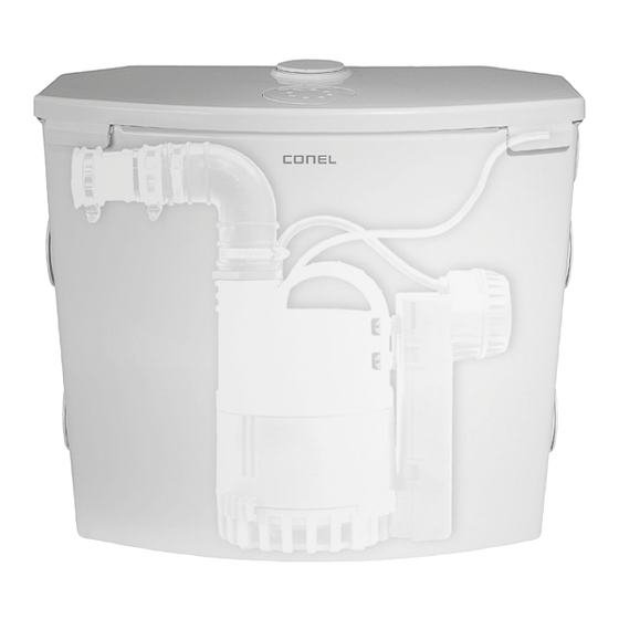
Scope of delivery | Technical data | Connections 5. Scope of delivery Synthetic tank with rubber feet, tank mounting supports/securing brackets, lid with vent integrated odor filter and overflow protection, FLOW 12 submersible pump with float switch and check valve, discharge line and hose connections adapters for washing machine and dishwasher, completely pre-assembled and wired ready for installation. -
Page 31: Level Control
Abmessungen See appendix fig. 2 7. Application > Conel wastewater lifting station FLOWBOX according to DIN EN 12050-2, installed above ground to drain sinks, washing machines and dishwashers, shower basins and bathtubs. > The FLOWBOX is exclusively for private use for the pumping of clear water, chemical-neutral grey water, faecal-free water and domestic sewage with solids of up to max. -
Page 32: Transport
Application | Transport | Electrical connection in the public sewer system is 35 °C and that you must ensure that the water is cooled accordingly The noise emission value is less than 70 dB (A). > > As with any electrical appliance, if due to the specific use a failure of the pump can cause damage (for example in the case of faulty operation, due to a power failure or a technical defect). -
Page 33: Set Up/Installation
Set up/installation | For ground set up 10. Set up/installation ATTENTION! The relevant standards must be observed! For use below the backwash level: > Guide the discharge line with a loop above the backwash level. > If the base of the discharge line loop is more than 5 m above the lifting unit, an additional check valve must be installed. - Page 34 Set up/installation | For ground set up Installation of securing brackets Keeps the lifting unit safely in place, even in case of flooding. 1. Place the lifting unit in the desired installation location. 2. Secure unit to the ground with the aid of the brackets (see appendix, fig. 4.1). Connection of discharge pipe 1.
-
Page 35: For Wall Suspension
Set up/installation | For ground set up | For wall suspension | For front wall installation Installation of a CONEL alarm system or a CONEL washing machine stop Optional accessories, available from your GC supplier. > Install the alarm contact sensor with mounting clamp on the intended retainer in the tank. -
Page 36: Commissioning
Commissioning | Maintenance 11. Commissioning ATTENTION! > The lifting unit is now operational. > Plug in the plug and carry out a function test: Allow water to flow into the tank. The lifting unit turns on as soon as the electrical power supply is established and the water level in the tank is above the switch on level. -
Page 37: Accessories
Optional rechargeable accumulators for mains-independent alarm signal. With alarm device including 5 m cable. KBN: FLOWAKS 13.2 CONEL rechargeable battery for alarm system Rechargeable battery to change the CONEL alarm system for network-independent operation. KBN: ABSBATT9 13.3 CONEL washing machine-stop alarm kit FLOW WKS Acoustic alarm with signalling unit for plugging in to a 230 V DIN socket, with integral 230 V earthed DIN socket into which the washing machine is plugged (l max. -
Page 38: Appendix
Appendix 14. Appendix Fig. 1: Performance curve Pump Curve 50 Hz H = total head Q = discharge volume Curve to ISO 9906 FLOW TP 12 Figure 7 (m³/h) [l/s] Fig. 2: Dimensions... - Page 39 Appendix Figure 3: Installation examples 3.1 Ground set up 95 mm Pump switching levels: ON = 100 mm OFF = 50 mm Note: Reference level is bottom of the tank. 3.2 Wall suspension 85 mm ATTENTION ! It must be ensured that the inlet line can run completely through a natural gradient and that no backwash occurs.
- Page 40 Appendix Fig. 4: Securing brackets 4.1 Floor mounting Keeps the lifting unit safely in place, even in case of flooding. 4.2 Wall mounting The tank can be suspended on a wall if floor mounting is not possible or desired.
- Page 41 Appendix Fig. 5: Exploded drawings 5.1 Lifting station...
- Page 42 Appendix 5.2 Pump with arrows ”inlet screen closed and open“ As of 10/2008, technical changes reserved.
-
Page 43: Spare Parts List
Spare parts 15. Spare parts Fig. 6 3 (seal) 11 (DN 50 seal) - Page 44 Spare parts Pos. Item no. Description Factory no. FLOW Venting kit including table YAE61705766 61705766 tennis ball YAE62665322 FLOW Odour filter 62665322 YAE11150002 FLOW Seal for upper inlet 11150002 YAE42485021 FLOW Lid 42485021 YAE11120556 FLOW Lid seal 11120556 YAE62665337 FLOW Discharge connection kit 62665337 FLOW Replacement pump with FLOWEP...
-
Page 47: Impressum
Gültig für: EU-Länder und Schweiz, nicht für UK. Imprint FLOW CUT BOX Installation and Operating Instructions © CONEL GmbH, Margot Kalinke-Str. 9, 80939 München, Phone: +49 89 31 86 87 80 FLOWBOX/2.1/03-17 All illustrations, dimensions, technical data and product information are correct at time of printing. - Page 48 Regal | Etikett | Barcode | Karton TOOLS Werkzeuge, Arbeitsmittel Trennscheiben | Werkzeugkoffer CLEAR Wasseraufbereitung Filtration | Enthärtung FLOW Pumpen mobile Tauchpumpen | Hebeanlagen CARE Chemiewirkstoffe Anwendungssysteme | Wartung | Reinigung | Instandhaltung | Baustoffe CONEL – der beste Freund des Installateurs.
Need help?
Do you have a question about the Flow Box and is the answer not in the manual?
Questions and answers