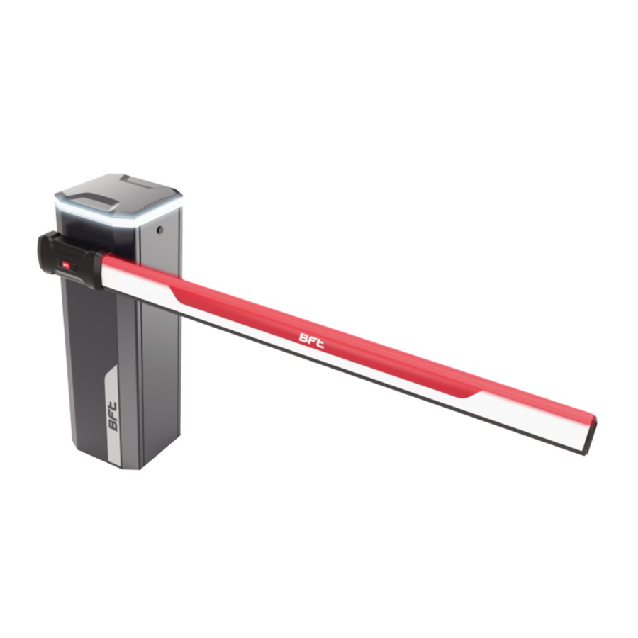
BFT Maxima Ultra 36 Installation And User Manual
Hide thumbs
Also See for Maxima Ultra 36:
- Instructions for installation, use and maintenance manual (21 pages) ,
- Quick reference manual (20 pages) ,
- Installation and user manual (41 pages)
Advertisement
BARRIERA AUTOMATICA
AUTOMATIC BARRIER
BARRIÈRE AUTOMATIQUE
AUTOMATISCHE SCHRANKE
BARRERA AUTOMÁTICA
Attenzione! Leggere attentamente le "Avvertenze" all'interno! Caution! Read "Warnings" inside carefully! Attention! Veuillez lire attentivement les Avertissements qui se trouvent à l'intérieur!
Achtung! Bitte lesen Sie aufmerksam die „Hinweise" im Inneren! ¡Atención¡ Leer atentamente las "Advertencias" en el interior! Let op! Lees de "Waarschuwingen" aan de binnenkant zorgvuldig!
Advertisement
Table of Contents

Summary of Contents for BFT Maxima Ultra 36
- Page 1 BARRIERA AUTOMATICA AUTOMATIC BARRIER BARRIÈRE AUTOMATIQUE AUTOMATISCHE SCHRANKE BARRERA AUTOMÁTICA Attenzione! Leggere attentamente le “Avvertenze” all’interno! Caution! Read “Warnings” inside carefully! Attention! Veuillez lire attentivement les Avertissements qui se trouvent à l’intérieur! Achtung! Bitte lesen Sie aufmerksam die „Hinweise“ im Inneren! ¡Atención¡ Leer atentamente las “Advertencias” en el interior! Let op! Lees de “Waarschuwingen” aan de binnenkant zorgvuldig!
-
Page 2: General Information
1. General information 1.1 INTRODUCTION Carefully read the handbook before installing and using the product, and before performing routine or corrective maintenance. The directions preceded by this symbol contain information of particular importance. Non- compliance with such directions can result in the loss of the contractual warranty. THE OPERATIONS THAT, IF CARRIED OUT INCORRECTLY, CAN POSE RISKS, ARE INDICATED WITH THE SYMBOLS: ELECTROCUTION CRUSHING... -
Page 3: Overall Dimensions
1. General information / 2. Installation 1.5 OVERALL DIMENSIONS LEFT barrier RIGHT barrier 2.1 INSTALLATION EXAMPLE 1) Single-phase line (2+G) x 1.5mm2 2) Transmitting Photocell 2 x 0.5 mm2 3) Receiving Photocell 4 x 0.5 mm2 4) Key selector switch 3 x 0.5 mm2 5) Receiver 4 x 0.5 mm2... -
Page 4: Electrical Connections
2. Installation 2.3 ELECTRICAL CONNECTIONS Open the cover and access inside the barrier to remove of the doors Remove the cover of the internal control unit Secure with cable ties Control board CSB-Xtreme Refer to the use and installation manual of the control unit - 11 -... - Page 5 2. Installation 2.4 BAR INSTALLATION Installation is mandatory in XL confi guration (supplied). M14x70 For STD version, it is optional (not supplied). Ø14 HYPHEN PS Ø6x12 4.2x16 Ø6 M6x20 Ø6 Ø14 BOOM PS Ø5 M5x8 2.5 BAR ALIGNMENT Adjustable bar holder Electrically connect the con- trol unit (see CSB-Xtreme Check that the bar is in horizontal...
-
Page 6: Optional Items
2. Installation 2.6 BAR BALANCING Before performing any task on the equipment, cut off the power supply. 24 mm Remove the screw which secures the lever DO IT ONLY WITH THE BAR MOUNTED AND POSITIONED VERTICALLY 45° 22 mm Bring the bar to verti- Check that the bar is balanced cal position at approximately 45°... -
Page 7: Installation
2. Installation 2.8 MANUAL OPERATION Before performing any task on the equipment, cut off the power supply. Manual release DO IT ONLY WHEN THE BAR IS MOUNTED RELEASE CRANK - 14 -... -
Page 8: Use And Maintenance
3. Use and maintenance 3.1 GENERAL SAFETY • The barrier is intended exclusively for vehicle use. Indicate and delimit any walkways using a specifi c sign. • Keep children, people and objects out of the operating range of the automation, in particular during operation. •... - Page 9 MAXIMA ULTRA 36 • BALANCING THE ARM BOOM PS BOOM PS Do not weigh the arm down by applying other accessories BTM-SKIRT ADJ-FOOT Spring coupling holes Springs calibration (APPROXIMATE DATA) TAB.1 The values in the table are the same for the version with lights.
-
Page 10: Registro Di Manutenzione
REGISTRO DI MANUTENZIONE MAINTENANCE LOG REGISTRE DES OPÉRATIONS D’ENTRETIEN INSTANDHALTUNGSPLAN RESISTRO DE MANTENIMIENTO Dati impianto / Installation data Installatore Installer Cliente Customer Matricola Serial number Data installazione Installation date Data attivazione Activation date Luogo Location Dati manutenzione / Maintenance date Data •... - Page 11 Data • Date Descrizione intervento • Intervention description Firma • Signature Tecnico • Technician Cliente • Customer Tecnico • Technician Cliente • Customer Tecnico • Technician Cliente • Customer Tecnico • Technician Cliente • Customer Tecnico • Technician Cliente • Customer Tecnico •...
- Page 12 INSTALLATORE INSTALLER INSTALLATEUR INSTALLATEUR INSTALATOR DATA DATE DATE DATUM FECHA ITALY...


Need help?
Do you have a question about the Maxima Ultra 36 and is the answer not in the manual?
Questions and answers