Table of Contents
Advertisement
Advertisement
Table of Contents

Related Manuals for A&D HV-C Series


Summary of Contents for A&D HV-C Series
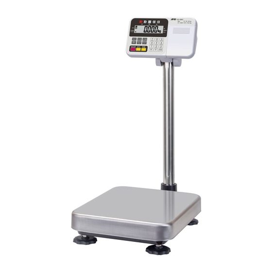
- Page 1 Digital Platform Scale Global models HV-15KC HV-15KCP HV-60KC HV-60KCP HV-200KC HV-200KCP HW-10KC HW-10KCP HW-60KC HW-60KCP HW-100KC HW-100KCP HW-200KC HW-200KCP Region - limited models HV-300KC HV-300KCP HV-600KC HV-600KCP HW-300KC HW-300KCP HW-600KC HW-600KCP 1WMPD4003471B...
- Page 2 © 2019 A&D Company Ltd. All rights reserved. No part of this publication may be reproduced, transmitted, transcribed, or translated into any language in any form by any means without the written permission of A&D Company Ltd. The contents of this manual and the specifications of the instrument covered by this manual are subject to change for improvement without notice.
-
Page 3: Table Of Contents
Contents Compliance..........................3 1.1. Compliance with FCC Rules....................3 Outline and Features ........................3 Precautions..........................5 3.1. Installing the Scale ........................5 3.2. Operating the Scale......................... 5 3.3. Storing the Scale........................6 Setting up and Installing the Scale..................... 7 4.1.1. Model-A Procedure to Assemble the Scale............... - Page 4 10.1.3. Setting Threshold Values (of Limits and Ranks) ..............36 10.1.4. Buzzer of Comparator Mode....................37 Auto-Tare...........................38 Built-in Printer of Type CP .......................39 12.1.1. Installing the Roll Paper......................40 ID Number and GLP.........................41 13.1. Setting the ID Number......................41 13.1.1. Display Character Table.....................41 13.2. Setting the Clock........................42 13.3.
-
Page 5: Compliance
1. Compliance 1.1. Compliance with FCC Rules Please note that this equipment generates, uses and can radiate radio frequency energy. This equipment has been tested and has been found to comply with the limits of a Class A computing device pursuant to Subpart J of Part 15 of FCC rules. These rules are designed to provide reasonable protection against interference when this equipment is operated in a commercial environment. - Page 6 The following parameters are stored in the scale even if the AC adapter or batteries are removed or the display is turned off (standby mode). Display mode (weighing unit) Unit mass of counting mode Total count and total mass value of accumulation function Preset limit values of comparator function Calibration data Parameters of the function table...
-
Page 7: Precautions
3. Precautions 3.1. Installing the Scale Consider the following conditions to get the most from your scale. Install the scale where the temperature and relative humidity are stable, there is no draft and a stable power source is available. Install the scale on a solid and level surface. Do not install the scale in direct sunlight. -
Page 8: Storing The Scale
3.3. Storing the Scale Do not disassemble the scale. Do not use solvents to clean the scale. Wipe it with a dry lint-free cloth or a lint-free cloth moistened with water and a mild detergent. The base unit can be cleaned with gentle running tap water. Do not scratch the base unit with a brush. -
Page 9: Setting Up And Installing The Scale
4. Setting up and Installing the Scale There are two ways of assembling (setting up) the HV-C/CP and HW-C/CP series. Assemble the scale according to the method-A procedure or method-B procedure. Models Reference S-model: HV-15KC, HV-15KCP, HW-10KC, HW-10KCP Method-A procedure to assemble the scale M-model: HV-60KC, HV-60KCP,... -
Page 10: Method-B Procedure To Assemble The Scale
4.1.2. Method-B Procedure to Assemble the Scale HV-300KC, HV-300KCP, HV-600KC, HV-600KCP, HW-300KC, HW-300KCP, HW-600KC, HW-600KCP This procedure is used to set up the above models. Accessory Step 2 Weighing Pan Note Display unit, pole and base unit are connected by Display unit cable. -
Page 11: Package Contents
5. Package Contents S-models L-models HV-15KC HV-200KC HV-200KCP HV-15KCP HW-100KC HW-100KCP HW-10KC Display unit HW-200KC HW-200KCP HW-10KCP Display unit Weighing pan M-models Display unit Weighing pan HV-60KC HV-60KCP HW-60KC HW-60KCP Weighing pan Base unit Caution Do not pull the load cell cable. Caution Do not pull the load cell cable. - Page 12 L2-models HV-300KC HV-300KCP Display unit HV-600KC HV-600KCP HW-300KC HW-300KCP HW-600KC HW-600KCP Caution The load cell cable is not connected when shipping. Weighing pan Caution Do not pull the load cell cable. Base unit Accessories Accessories supplied depend on the scale. Refer to "5.1.
-
Page 13: Accessories And Options List
Type C and CP Type C Scale with "C" or "CP" at the end of model name. Scale with "C" at the end of model name. Batteries (Not included) AC adapter Please confirm that the AC adapter type is correct for your local voltage and receptacle type. -
Page 14: Options List
5.1.2. Options List Order code Option name Models HV-300KC, HV-300KCP, Extension load cell cable HV-600KC, HV-600KCP, HVW-02 for L2-models, 5 m HW-300KC, HW-300KCP, HW-600KC, HW-600KCP HVW-02CB USB interface HVW-03C RS-232C interface All models Comparator relay output / Buzzer / HVW-04C Contact input HV-15KC, HV-15KCP,... -
Page 15: Installing The Batteries For Type C
5.2. Installing the Batteries for Type C AC adapter Step 1 Turn off the display. Step1 Remove the AC adapter. AC adapter Please confirm that the AC adapter type is correct for your local voltage and receptacle type. The AC adapter may not be provided for some areas. -
Page 16: Removing The Pole
5.3. Removing the Pole Caution Remove the AC adapter and batteries before removing the pole. When removing the load cell cable, do not pull on the load cell cable connector forcibly and do not pull on the wires of the cable. Do not pull the load cell cable. Do not bend the cable forcibly. Take care that the load cell cable does not touch the weighing pan inside the base unit. - Page 17 Hex wrench Step 7 Arrange the cable so it does not touch the weighing Hex screws pan in the base unit. If the cable is untied, the straight length of S-models is approximately 1.5 m, and the straight length of M-models and L-models is approximately 2.5 m.
-
Page 18: Method-B Procedure To Remove The Pole
5.3.2. Method-B Procedure to Remove the Pole HV-300KC, HV-300KCP, HV-600KC, HV-600KCP, HW-300KC, HW-300KCP, HW-600KC, HW-600KCP Step 1 Turn the scale off. Cable cover Cable clamp Remove the AC adapter and batteries. . Connector Step 2 Open the rear cover of the display unit. Gently disconnect the load cell cable connector Load cell cable vertically. -
Page 19: Grounding The Scale
5.4. Grounding the Scale When using where there may be static electricity, ground the scale. The grounding method depends on the model. Refer to the list below and ground the scale properly. These procedures are only for the grounding part of the scale. Models Reference Method-A procedure... -
Page 20: Description Of Each Part
6. Description of Each Part S-models M-models HV-15KC Serial No. (on the side) HV-60KC HV-60KCP Serial No. (on the side) HV-15KCP Display unit HW-60KC HW-60KCP Display unit HW-10KC L-models HW-10KCP HV-200KC HV-200KCP HW-100KC HW-100KCP Pole HW-200KC HW-200KCP Pole Leveling foot Base unit Weighing pan ( SUS430 ) Display unit of type C... - Page 21 L2-models HV-300KC HV-300KCP Serial No. (on the side) HV-600KC HV-600KCP HW-300KC HW-300KCP Display unit HW-600KC HW-600KCP Pole Bubble spirit level Leveling foot Base unit Weighing pan ( SUS430 ) Display unit of type C Display unit of type CP CAL switch Type CP Calibrate the scale to weigh correctly.
-
Page 22: Display And Symbols
6.1. Display and Symbols Display and Symbols Description Stability mark When the current weighing value is stable, this mark is displayed. It means the scale is in the proper condition for reading weighing value. Zero point mark The zero point is the reference point for weighing. When the ZERO key is pressed with nothing on the weighing pan, this mark and a zero value are displayed. - Page 23 Display and Symbols Description While setting a preset tare (Example) Input a tare value using the numerical keys. Store the new tare value using the ENTER key. Function settings (Example) Select the item using the MODE key and enter the item using the ENTER key.
-
Page 24: Keys
6.2. Keys Display and Symbols Description ON/OFF key to show or hide the display alternately. When the scale is turned on, the electric power is supplied to the electric circuit inside the scale. When the scale is turned off, the scale is in standby status. At this time, only minimum power consumption of the waiting mode and power consumption of AC adapter connected to the AC socket are consumed. - Page 25 Display and Symbols Description Press and hold the SET key and press the TARE key. Use these keys to enter preset tare setting mode. Press and hold the SET key and press the PRINT key. Use these keys to perform paper feed at the built-in printer. (Type CP) Press and hold the SET key and press the M+ key.
-
Page 26: Basic Operation
7. Basic Operation 7.1. Turning the Scale On/Off and Weighing 7.1.1. When Using the AC Adapter Step 1 Ground the scale. Step 2 Confirm that nothing is placed on the weighing pan. Step 3 Confirm that local voltage and receptacle type are correct. Step 4 The scale is turned on or off using the ON/OFF key. -
Page 27: When Using The Batteries For Type C
7.1.2. When Using the Batteries for Type C Step 1 Install four new batteries. Refer to "5.2. Installing the Batteries for Type C". Step 2 Confirm that nothing is placed on the weighing pan. Step 3 The scale is turned on or off using the ON/OFF key. Step 4 Check the accuracy of weighing. -
Page 28: Tare Function To Display Net Value
Tare Function to Display Net Value The tare function is used to cancel the mass value of a tare weight and to display the net value, when a container (tare weight) to hold the article to be weighed is placed on the weighing pan. -
Page 29: Switching The Mode
7.3. Switching the Mode When accumulation data is stored in the scale, the number of accumulations and an accumulation value can be displayed. The weighing unit used when turned on is the last weighing unit used before turning off. Ib-oz display is available only with HV-15KC, HV-15KCP, HW-10KC and HW-10KCP. kg weighing Counting mode Unit mass storing mode... -
Page 30: Counting Mode
8. Counting Mode The counting mode is the function to convert the total mass value (total weight) of articles to a count, when each article has the same mass value. To use this function, store a unit mass in advance. Even if the AC adapter or the batteries is removed, the unit mass is maintained in non-volatile memory. -
Page 31: Counting The Number Of Articles
8.2. Counting the Number of Articles Step 1 Press the key to display the unit MODE Step 2 Store the unit mass of the article. Refer to "8.1. Storing a Unit Mass". Storing a unit mass Container Weighing pan Step 3 Place the container on the weighing pan. Press the key. -
Page 32: Accumulation Function
9. Accumulation Function The accumulation function can display the accumulation count and accumulation mass value of articles to be weighed. Maximum accumulation count is 999 times. The accumulation function is displayed with up to 6 digits and cannot display the leading digits of 7 or more. - Page 33 Parameters of Function Table and Word Definition "near zero" is within ±4 digits (four times the minimum weighing value that can be weighed) from zero point in the weighing unit "kg". Item and Description Parameter Accumulation function not used. When the weighing value is a positive stable value and not "near zero", if the M+ key is pressed, the value is accumulated.
-
Page 34: Comparator
10. Comparator The comparator function can select a mode from "Five-level comparator mode", "Three-level comparator mode (Upper and lower limit mode)" and "Seven-level comparator mode (Ranking mode)". Each comparator mode compares the weighing value against the preset threshold values and outputs the results using LEDs (yellow, green and red). -
Page 35: Setting A Mode And Method
10.1.1. Setting a Mode and Method Step 1 Turn off the scale using the ON/OFF key. Display off While pressing and holding the TARE key, Press and hold press the ON/OFF key to enter the setting mode. Then the software version Press is displayed. -
Page 36: Comparison And Formula
10.1.2. Comparison and Formula Judgment is performed using the formulas below. The result is displayed to the comparator indicator and output to option interface. Five-Level Comparator Mode Relay Result Comparison formula output Displayed value < LOLO limit value or, LOLO LOLO Displayed value <... - Page 37 Threshold values of limits and ranks are common to both the weighing and counting mode. These threshold values are maintained even if the power supply is off. Ignore the decimal point when setting threshold values of limits and ranks. Comparison is performed in order from the top row to the bottom of each table. These threshold values are not judged.
-
Page 38: Setting Threshold Values (Of Limits And Ranks)
10.1.3. Setting Threshold Values (of Limits and Ranks) Step 1 While pressing and holding the SET key, press the COMP key to enter the comparator value setting mode. Step 2 Input a parameter for the comparison method using the numerical keys of to _9_, ENTER key to store and proceed, key to cancel and SET key to alternate between +/-. -
Page 39: Buzzer Of Comparator Mode
10.1.4. Buzzer of Comparator Mode Installing the optional HVW-04C on the scale allows the buzzer to sound in conjunction with LEDs according to the comparison result. The buzzer can be set by using the _1_, _2_, _3_, numerical keys when of the function table is displayed. -
Page 40: Auto-Tare
11. Auto-Tare The HV/HW-C/CP series has an auto-tare function to be used with the comparator mode enabled. Using this function in check weighing, the scale automatically tares, then displays OK for a certain amount of samples and repeats this process for the next weighing. Start with display zero value after tare operation. -
Page 41: Built-In Printer Of Type Cp
12. Built-in Printer of Type CP Specify the parameter of "Built-in printer output mode ( )" in the function table to use the printer in advance. Specify the parameters of "Setting the clock ( )" and "Time and date adding )"... -
Page 42: Installing The Roll Paper
Printing example for accumulation result ( accumulated data and count ). If the PRINT key is pressed while the accumulation result ( accumulated data and count ) is displayed, this result is printed. 12.1.1. Installing the Roll Paper Step 1 Pull the printer cover toward you to open it. Step 2 Install the roll paper so that the end of the paper is at the top. -
Page 43: Id Number And Glp
13. ID Number and GLP The ID number is used to identify the scale when Good Manufacturing Practice (GMP) or Good Laboratory Practice (GLP) is used. The following GMP data is output to the built-in printer (HV-CP/HW-CP series) or a personal computer using the RS-232C interface. Results of calibration ("Calibration report") Results of calibration test ("Calibration test report") "Start block"... -
Page 44: Setting The Clock
13.2. Setting the Clock The clock can only be set for built-in printer models (Type CP). Step 1 Turn off the display. While pressing and holding the TARE key, press the ON/OFF key to turn the display on and enter function setting mode. -
Page 45: Gmp Report
13.3. GMP Report If the GMP report is printed to an AD-8121B printer or AD-8127 printer, use "Format of AD-8121B or AD-8127, " in the function table. Use "MODE 3" for the AD-8121B. Use "DUMP print mode" for the AD-8127. If the GMP report is output to a personal computer, use "the general format, "... - Page 46 Calibration test report The calibration test mode is used to compare a calibration weight with the calibration test data weighed by the scale. Note Press for 5 This test does not perform calibration. Press seconds or more Step 1 In the weighing mode, press and hold the CAL switch until appears, and then release the switch.
- Page 47 AD-8127 format General format A & D <C Manufacture > MODE L H V - 1 5 K C <C > Model S / N 6 A 6 1 2 3 4 5 6 <C > Serial number A B C D E F <C ID number >...
- Page 48 End block Press and hold Step 3 Press and hold the PRINT key until appears, and release then the key. The scale outputs the "End block." To output the "End block" Step 4 The scale automatically returns to the weighing mode. Title block AD-8127 format General format...
-
Page 49: Calibration (Adjusting The Scale)
14. Calibration (Adjusting the Scale) The scale is an instrument that weighs the "weight" and displays its "mass". Calibration is the adjustment function so that the scale can weigh correctly. Three steps of calibration are available Gravity Acceleration Correction Function to correct the scale’s local gravity acceleration, so that the scale functions correctly when the calibrated scale has been moved to a distant place. -
Page 50: Gravity Acceleration Table
14.1. Gravity Acceleration Table Amsterdam 9.813 m/s Manila 9.784 m/s Athens 9.800 m/s Melbourne 9.800 m/s Auckland, NZ 9.799 m/s Mexico 9.779 m/s Bangkok 9.783 m/s Milan 9.806 m/s Birmingham 9.813 m/s New York 9.802 m/s Brussels 9.811 m/s Oslo 9.819 m/s Buenos Aires 9.797 m/s... -
Page 51: Complete Calibration Procedure
14.2. Complete Calibration Procedure 14.2.1. Gravity Acceleration Correction Step 1 Turn on the display. CAL switch Open the rear cover of the display unit. Locate the CAL switch inside. Press the switch to enter calibration mode. Then is displayed. Step 2 Press the key to enter gravity acceleration MODE correction mode. -
Page 52: Calibration Of The Zero Point
14.2.3. Calibration of the Zero Point Weighing mode Step 3 After 30-minute warm up, press the CAL switch to display CAL switch Press the ENTER key to display Step 4 Confirm that nothing is placed on the weighing pan. Wait for the stability mark to be displayed. Press the ENTER key to store Nothing is placed on the pan the current condition as the zero point. -
Page 53: Function Table
15. Function Table Item Parameter The function table is used to store and refer items that determine the performance of the scale. Each item has a parameter. The parameters are stored in the scale even if the AC adapter or batteries are removed or the display is turned off (standby mode). -
Page 54: Parameter List
15.2. Parameter List For the HV-C/CP series NTEP/Measurement Canada version, the shaded items in the below table cannot be changed by the user, so these items are not displayed. Class Items Parameter Details and usage All the keys function. Key lock keys function. - Page 55 Class Items Parameter Details and usage 0 second 0.5 seconds 1.0 second 1.5 seconds Interval until 2.0 seconds making automatic tare 2.5 seconds 3.0 seconds 4.0 seconds 5.0 seconds 10 seconds Tare on initial load Accumulates by key when the value is +, excluding "near zero"...
- Page 56 Class Items Parameter Details and usage Five-level comparator mode Comparator mode Three-level comparator mode (upper and lower limit mode) Seven-level comparator mode (ranking mode) No comparison All data is compared. Stable data is compared. Comparator judgment condition All data is compared except "near zero".
- Page 57 Class Items Parameter Details and usage Stream mode (commands) Output by command from OP-ch1 or OP-ch2. Commands to be Output by command from OP-ch1. output are as follows : Q, A, N Output by command from OP-ch2. Command is output by the key.
- Page 58 Class Items Parameter Details and usage Stream mode (commands) Output by command from OP-ch1 or OP-ch2. Commands to be Output by command from OP-ch1. output are as follows : Q, A, N Output by command from OP-ch2. Command is output by the key.
- Page 59 Class Items Parameter Details and usage Do not print Output by command from OP-ch1 or OP-ch2. Commands to be Output by command from OP-ch1. output are as follows : Q, A, N Output by command from OP-ch2. Print data by the key.
-
Page 60: Initializing Parameters Of The Function Table
15.3. Initializing Parameters of the Function Table The following procedure can reset to the factory settings parameters stored in the function table. Parameters of the comparator are reset as well. Step 1 Turn off the display using the ON/OFF key. Step 2 While pressing and holding the TARE key, press the ON/OFF key to display Step 3 Press the SET key to display... -
Page 61: Options
16. Options The scale is equipped with OP-ch1 and OP-ch2 for communication options, and OP-ch3 only for comparator relay output. Those options can be combined freely. Combinations such as HVW-02BC x 2, HVW-02CB + HVW-03C or HVW-03C x 2 are possible. Only an HVW-04C can be installed to the slot for OP-ch3. -
Page 62: Hvw-02Cb, Usb Interface
16.2. HVW-02CB, USB Interface The HVW-02CB enables duplex communication using a USB interface. The connector is type B. To connect the HVW-02CB to a computer, a commercially "type A male - type B female" cable can be used. To communicate between the scale and a computer using the USB interface, it is necessary to install the specified driver software to a computer. - Page 63 Reading the COM port Number ( Check after software is installed to computer.) Step 1 Press the START button and open the control panel. Step 2 Open "Hardware & Sound" and "Device Manager" in that order. Step 3 Expand the "Ports (COM & LPT)" by double-clicking to display the COM port number.
-
Page 64: Hvw-03C, Rs-232C Interface
16.3. HVW-03C, RS-232C Interface The HVW-03C enables duplex communication using the RS-232C interface. The DCE (Data Communication Equipment) connector is type DSUB-9P. To connect the HVW-03C to an external device, it is necessary to use a commercially available communication cable. AX-KO2466-200 (2 m) / AX-KO2466-500 (5 m) / AX-KO2466-1000 (10 m) When confirming the communication format, refer to "16.5. -
Page 65: Hvw-04C, Comparator Relay Output / Buzzer / Contact Input
16.4. HVW-04C, Comparator Relay Output / Buzzer / Contact Input Output terminal of comparator & relay Contact input terminal The buzzer is mounted on the board. The specifications of the solid state relay are as follows : : 50 V DC Maximum voltage Socket on the board : 100 mA DC... - Page 66 External Contact Input Plug and Wiring Example An external contact input plug is included. Solder the plug and electrical wires according to the circuit diagram below. : The function of the switch can be assigned at the external contact input in the function table.
-
Page 67: Communication Format
16.5. Communication Format Data format S T , + 0 0 0 0 0 . 0 0 k g C Header Data Unit Terminator There are 4 headers for the weighing data. ST : Stable weighing data QT : Stable counting data US : Unstable weighing data OL : Out of weighing range The data consists of 9 characters including the polarity and decimal point. - Page 68 Print key mode ( Specify in the function table. When the weighing value is stable, data is output by pressing the PRINT key. At this time, the display flashes once to indicate that the data is output. Auto-print mode + data ( Specify in the function table.
-
Page 69: Command Mode
16.5.1. Command Mode In the command mode, the scale is controlled by commands that come from an external device such as a computer. Command List Command Description Remarks Requests data output immediately. Zeros the scale when the weighing value is stable. Same as the key. - Page 70 Command Description Remarks In five-level comparator mode : Not used In three-level comparator mode : Not used In seven-level comparator mode : The threshold value of rank 5 is stored. In five-level comparator mode : HIHI limit value is stored. In three-level comparator mode : HI limit value is stored.
- Page 71 Command Examples The examples below are for the function setting (Reply to commands). The character means "Space (20h)". To request data output immediately. Command Q C S T , + 0 0 1 2 . 3 4 5 k g C Reply Stable positive data U S , + 0 0 0 7 .
- Page 72 To output the number of accumulations. Command N C N , + 0 0 0 0 0 1 4 0 Reply To clear accumulation. Accumulated data and number of accumulations are set to zero. C A C Command C A C Reply To set the ID number.
- Page 73 To output H1 value. Five-level comparator mode ..... HI limit value is output. Three-level comparator mode ..Not used Seven-level comparator mode ..Upper threshold value of rank 3 is output. ? H 1 C Command H 1 , + 0 0 0 3 0 0 C Reply To output L1 value.
- Page 74 To set H2 value. Five-level comparator mode ..... HIHI limit value is stored. Three-level comparator mode ..HI limit value is stored. Seven-level comparator mode ..The threshold value of rank 4 is stored. Input the parameter of 6 digits excluding the polarity and decimal point. H 2 , [ parameter ] Template H 2 , + 0 0 0 4 0 0 C...
- Page 75 Response when is specified in the function table is used and a command response is active, the following response may be output. When the Z command is executed with an unstable weighing value and cannot be finished, the response I is returned. Command Reply The scale is not in a condition that zero operation is possible.
-
Page 76: Using Ufc (Universal Flex Coms) Function
16.6. Using UFC (Universal Flex Coms) Function The UFC function allows you to print out using the format enabled for the printer (UFC format). The UFC format data can be output through an RS-232C or USB interface. The scale can store the UFC format as text data. The format can use variable parameters as a part of text data. - Page 77 Data repeated When the control codes $SP, $CR and $LF can be used with " and a number (of two digits maximum)", these codes will be repeated the number of times designated. $LF 9 Example where $LF is repeated 9 times : $SP 12 Example where space is repeated 12 times : Link mark &...
- Page 78 $AN of variable parameter Example of accumulation count : 123 counts + 1 2 3 9 digit accumulation count $CP of variable parameter Example of HIHI result H I 2 3 digits Example of HI result H I 1 3 digits Example of OK result 2 digits Example of LO result...
-
Page 79: Specifications
17. Specifications HV-C/CP Series (Weighing capacity of 15 kg to 220 kg) HV-15KC HV-60KC HV-200KC Models HV-15KCP HV-60KCP HV-200KCP Weighing capacity [kg] Min. weighing (1 digit) [kg] 0.001 0.002 0.005 0.005 0.01 0.02 0.02 0.05 Weighing capacity [lb] Min. weighing (1 digit) [lb] 0.002 0.005 0.01 0.01 0.02... - Page 80 HW-C/CP Series (Weighing capacity of 10 kg to 220 kg) HW-10KC HW-60KC HW-100KC HW-200KC Models HW-10KCP HW-60KCP HW-100KCP HW-200KCP Weighing capacity [kg] Min. weighing (1 digit) [kg] 0.001 0.005 0.01 0.02 Weighing capacity [lb] Min. weighing (1 digit) [lb] 0.002 0.01 0.02 0.05...
- Page 81 HV-C/CP Series (Weighing capacity of 300 kg to 600 kg) HV-300KC HV-600KC Models HV-300KCP HV-600KCP Weighing capacity [kg] Min. weighing (1 digit) [kg] 0.05 Number of samples in counting 5 (can be changed to 10, 20, 50, 100) mode [pieces] Max.
- Page 82 HW-C/CP Series (Weighing capacity of 300 kg to 600 kg) HW-300KC HW-600KC Models HW-300KCP HW-600KCP Weighing capacity [kg] Min. weighing (1 digit) [kg] 0.05 Number of samples in counting 5 (can be changed to 10, 20, 50, 100) mode [pieces] Max.
- Page 83 Dimensions S-models HV-15KC HV-15KCP HW-10KC HW-10KCP (494) 43 (366) M-models HV-60KC HV-60KCP HW-60KC HW-60KCP (640) (750) 43 Unit: mm HV/HW-C/CP Series Page 81...
- Page 84 L-models HV-200KC HV-200KCP HW-100KC HW-100KCP HW-200KC HW-200KCP (746) 43 (750) L2-models HV-300KC HV-300KCP HV-600KC HV-600KCP HW-300KC HW-300KCP HW-600KC HW-600KCP (943) (942) 76 Unit: mm Page 82 HV/HW-C/CP Series...
-
Page 85: Maintenance
18. Maintenance Refer to "3. Precautions" regarding use. Refer to "14. Calibration (Adjusting the Scale)" regarding precision weighing. Periodically confirm the accuracy of the weighing. Calibrate the scale, if it has been moved to another location or the environment has changed. 18.1. -
Page 86: Index
19. Index _.................21 Bit length, Parity 1........... 54 Stability mark............20 Bit length, Parity 2........... 54 Battery mark.............20 Bubble spirit level ............7, 8, 18, 19 Comparator indicator ....... 20, 34 Built-in printer communication format ....54 Command, Request H1 value....67, 71 Built-in printer label mode ........ - Page 87 Dimensions ................77 - 82 Command, Set ID number......67 Display ...................77 - 80 GMP output 1..........55 Display character................41 GMP output 2..........56 Display unit..............9, 10, 18, 19 GMP print............57 Display unit cover AXP-3003217D ......9, 10, 11 Installing driver software.............. 60 Double size ..........
- Page 88 Automatic power off........52 Stability band width ........52 Pole ...................14, 18, 19 Stabilization level ........52 Automatic power on........52 Stand for the display unit FW-15........12 Power on tare................25 Status of LED when turning on display ....54 Power on zero................25 Stability band width.........
- Page 89 MEMO HV/HW-C/CP Series Page 87...
- Page 90 MEMO Page 88 HV/HW-C/CP Series...
- Page 92 3-23-14 Higashi-Ikebukuro, Toshima-ku, Tokyo 170-0013, JAPAN Telephone: [81] (3) 5391-6132 Fax: [81] (3) 5391-1566 A&D ENGINEERING, INC. 1756 Automation Parkway, San Jose, California 95131, U.S.A. Telephone: [1] (408) 263-5333 Fax: [1] (408)263-0119 A&D INSTRUMENTS LIMITED Unit 24/26 Blacklands Way, Abingdon Business Park, Abingdon, Oxfordshire OX14 1DY United Kingdom Telephone: [44] (1235) 550420 Fax: [44] (1235) 550485 A&D AUSTRALASIA PTY LTD...
Need help?
Do you have a question about the HV-C Series and is the answer not in the manual?
Questions and answers