IPC PW-C25 Service Manual
230v/400v/230v 50hz.
Hide thumbs
Also See for PW-C25:
- Operating instructions manual (116 pages) ,
- Manual (116 pages) ,
- User manual (108 pages)

Related Manuals for IPC PW-C25


Summary of Contents for IPC PW-C25
- Page 1 Service Manual Rev.1.0 January 2013 PW-C25 & PW-C25P Models 1509P-M 230V 50Hz I1509P-M 230V 50Hz 1813P-T 400V 50Hz I1813P-T 400V 50Hz I1310P4-M 230V 50Hz...
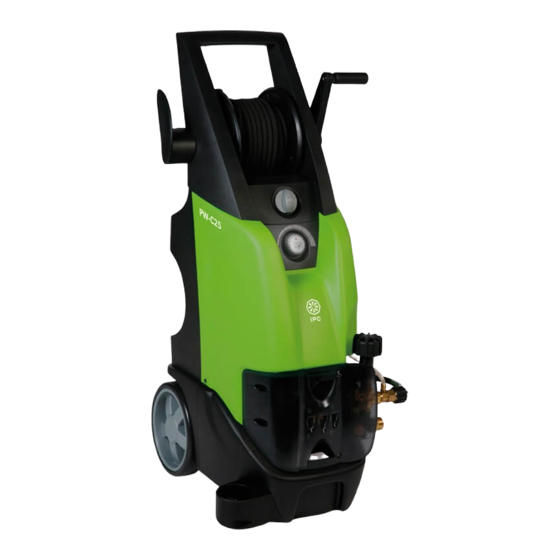
- Page 2 PW-C25 / PW-C25P outer layout High pressure hose – spray gun – lance Hose reel handle High pressure outlet Hose reel rotation lock Main switch 0-I Chemical tap and regulator Pressure adjust Lance holder Pressure gauge Refill cap Water outlet fitting...
- Page 3 PW-C25 / PW-C25P inner layout Standard accessories set, that includes the inlet water filter and “garden” quick inlet fitting. Main switch Chemical tap and dose Electric motor starting capacitor Electric motor Electric enclosure Pressure gauge Chemical injector Oil cap for handling and...
- Page 4 PW-C25 / PW-C25P electric box components layout Electric box for wiring the electric motor, the starting capacitor, the total stop switch and the power cord. Electric box for on – off main switch Pag. 4...
- Page 5 Service Manual Ip Cleaning S.p.A. Viale Treviso, 63 – 30026 Summaga di Portogruaro – VENICE – ITALY Tel. +39 0421 205511 (r.a.) – Fax +39 0421 204227 Internet address: www.ipcportotecnica.com e-mail address: infoipcportotecnica@ipcleaning.com INDEX Topics 1. The machine doesn’t starts Page 1a No electrical connection 1b No electrical supply to the electric motor or...
- Page 6 4. Poor detergent delivery Page 4a Detergent tap closed/off or clogged 4b Empty detergent tank or nozzle not set in detergent mode 4c The check valve of the detergent circuit is sticky or clogged 4d High pressure outlet pipes clogged or too much extended (over 20 m). Wear and tear of the detergent nozzle 4e Pressure regulator is not set at maximum position 5.
- Page 7 1. The machine doesn’t starts 1) TROUBLE: Rotating the main switch “0 – I” (A) the high pressure cleaner doesn’t starts or starts, but suddenly stops after a while. CAUSES: 1a No electrical connection 1b No electrical supply to the electric motor or motor thermal sensor overload intervened or burnt fuses 1c The micro-switch of bypass valve not working (only for machine with total stop system)
- Page 8 - check using a multimeter, the conductivity of the main switch contacts, rotate the switch knob to position “I” and in case of problems, replace the switch with a new component. To open the electric enclosures, proceed as following described: Opening: 1.
- Page 9 - If the thermal sensor of the electric motor is intervened, the electric motor is disconnected and the machine cannot work. The thermal sensor, intervenes when the motor winding temperature is over 155°C and in order to cool it down and allows its automatic reset, are required some minutes with the electric motor off.
- Page 10 Electric diagrams Single phase by-pass Single phase total stop Pag. 10...
- Page 11 Three phase by-pass Three phase total stop On which : • IQ = Main switch of the power supply socket • F = Fuses of the power supply socket • CV1 = Machine power cord • IG = Machine main switch •...
- Page 12 1c Total stop versions have a micro-switch “S” that controls the contactor “C” on three phase models and that controls directly the electric motor on single phase models, hence makes the pump and motor unit to start and to stop accordingly with the position of the spray gun trigger: When the spray gun trigger is activated, and the lance is ready to spray water, the micro- switch “S”...
- Page 13 1d The contactor “C” is installed only on three phase or P4 models and power supplies the electric motor accordingly to the status of the micro-switch “S” and main switch “IG” for machine total stop version and only the status of main switch “IG” for machines by pass version. Check using a multimeter if the contactor coil “A1-A2”...
- Page 14 2. No water jet at the lance nozzle 2) TROUBLE: No water jet sprayed from the lance nozzle. CAUSES: 2a Bad or missing water feeding connection 2b Inlet water filter clogged 2c Air intake from the water feeding circuit 2d Pump head valves ceased 2e High pressure nozzle clogged REMEDIES: Check the supply water flow (l/min), in order to ensure that supply water available is...
- Page 15 Check the water circuit that connects the water tap to the high pressure pump inlet, particularly check that fittings are properly tightened and not leaking water. This model has not capacity to intake water from a tank placed lower than the machine inlet fitting, hence this machine can only to intake the water from a tank placed above than the machine water inlet fitting.
- Page 16 The nozzles are colored with different colors to make possible the identification of their size, the part number description include the color information (see the part manual for PW-C25). We recommend the high pressure nozzle replacement every 200 hours or any time the machine working pressure become 20% lower than rated pressure.
- Page 17 3. No pressure to the lance 3) TROUBLE: The high pressure pump rotates, but doesn’t achieve the rated pressure or the pressure is not stable and fluctuates. CAUSES: 3a Defective water feeding connection 3b Inlet water filter clogged 3c Air intake from the water feeding circuit 3d Pump head valves ceased or worn 3e Lance nozzle set in low pressure mode (detergent mode) 3f High pressure nozzle worn or deformed...
- Page 18 3c Check the water circuit that connects the water to the high pressure pump inlet, particularly check that fittings are properly tightened and not leaking water. In case of leakages, proceed with the circuit repair. If the machine is in-taking water from an external tank, being its high pressure pump, not designed for self priming, is possible that its working pressure being lower and the machine can operate under this condition only temporarily, we do not recommend to use this machine continuously as self-priming.
- Page 19 3e Check the lance head (nozzle) position, it must be set in high pressure mode, not in detergent mode; during the detergent mode the water flow is discharged without pressure. Detergent mode High pressure mode 3f Replace the high pressure nozzle with a new genuine part. Check the spare part manual to identify the correct nozzle size.
- Page 20 3g Check if the pressure adjusting knob is set to maximum position. The position maximum is when the knob it fully rotated clockwise. 3h Repair the pressure adjusting valve (by pass valve) by replacing its cartridge that is part of the dedicated repairing kit.
- Page 21 Slide out the fixation bolt of The by-pass valve is so To disassemble the by-pass the by-pass disassembled, if necessary seat, push it out with the it can be replaced with a help of a screwdriver, as in new one. the picture.
- Page 22 After replaced the by-pass valve kit, will be necessary to readjust the machine maximum working pressure. The pressure adjustment can be done trough the adjusting screw as indicated in the following picture: Before adjust the bypass, maximum pressure setting, ensure that the pressure adjust knob is completely screwed-in.
- Page 23 Replace the high pressure pump gaskets kit and ensure that the ceramic pistons are not damaged. If ceramic pistons are cracked, replace them following the instruction as described in the paragraph 5c. Unscrew the 6 screws that hold the pump head Pull out the pump head Remove the pump head Extract the seals packing using the extractor...
- Page 24 4. Poor detergent delivery 4) TRUBLE: Poor detergent delivery CAUSES: 4a Detergent tap closed/off or clogged 4b Empty detergent tank or nozzle not set in detergent mode 4c The check valve of the detergent circuit is sticky or clogged 4d High pressure outlet pipes clogged or too much extended (over 20 m) 4e Pressure regulator is not set at maximum position 4f Wear and tear of the detergent nozzle REMEDIES:...
- Page 25 4b Refill with detergent the chemical tank if it is empty; we recommend to use only the detergents listed in the catalogue. Switch the head to the lance in detergent mode (LOW). 4c Dismantle and clean the detergent check valve. Unscrew and dismantle the detergent check valve placed at the machine outlet.
- Page 26 If using an high pressure hose longer than 20 m, the detergent suction can result compromised, since the Venturi system cannot work. At the same, a wrong functioning occurs when the high pressure outlet circuit of the machine is clogged or when using not genuine accessories. Reduce the length of the high pressure hose at maximum 20 m and ensure that there are not obstruction to the outlet circuit that causes counter pressure, hence not allowing the functioning of the Venturi system.
- Page 27 5. Oil and water emulsion phenomena to the high pressure pump oil 5) TROUBLE: The oil, inside of the high pressure pump looks white color (oil and water emulsion phenomena) CAUSES: 5a Extremely high environment humidity percentage 5b High pressure pump gaskets worn 5c High pressure pump pistons damaged REMEDIES: 5a Replace the pump oil using oil quality SAE 20W40:...
- Page 28 5b Replace the pump water gaskets as described in the section 3i 5c Replacement of the pump pistons: Check if pistons are cracked Unscrew the piston lock screw Slide out the damaged piston Check the o-ring wear If the o-ring is wear and tear Assemble the new piston and replace it with a new one.
- Page 29 6. The total stop system doesn’t intervenes (only for machines having this option) 6) TROUBLE: When the spray gun trigger is released, the pump and motor unit does not stop automatically or does not restart, when the trigger is reactivated. CAUSES: 6a Water leaks from the high pressure outlet circuit.
- Page 30 Periodical maintenance Every Every Every Every Every Every Every 100h 200h 300h 500h year Check the power cord and the high pressure quick couplings. F i r s t p u m p o i l r e p l a c e m e n t P u m p o i l r e p l a c e m e n t W a t e r f e e d i n g f i l t e r s c l e a n i n g Pump’s w ater gask ets r eplacement...
Need help?
Do you have a question about the PW-C25 and is the answer not in the manual?
Questions and answers