Table of Contents
Advertisement
Advertisement
Table of Contents

Related Manuals for Witschi ANALYZER Q1


Summary of Contents for Witschi ANALYZER Q1
- Page 1 ANALYZER Q1 INSTRUCTION MANUAL Please read before you work with the device!
- Page 2 Witschi Electronic Ltd. Bahnhofstrasse 26 3294 Büren an der Aare Switzerland Phone: +41 (0)32 - 352 05 00 Fax: +41 (0)32 - 351 32 92 Internet: www.witschi.com E-Mail: welcome@witschi.com Original Manual 26.6410D35e Document No. Rel. 1.2 August 2017 Last modification:...
-
Page 3: Table Of Contents
Mains Connection........................... 9 Printer Connection ..........................9 Language ..............................9 GENERAL OPERATION .......................... 10 Switching the Analyzer Q1 On and Off ....................10 Selection of a Measurement Function ....................10 Parameter Settings ..........................11 Help ..............................12 RATE MEASUREMENT OF QUARTZ WATCHES ..................13 General Introduction .......................... - Page 4 18.2 Installation ............................36 MAINTENANCE ............................ 36 TECHNICAL DATA ..........................36 20.1 Measurement Functions ........................36 20.2 Additional Functions ..........................39 20.3 Options ..............................39 20.4 General Data ............................39 ACCESSORIES ............................40 Page 4 Analyzer Q1 Witschi Electronic Ltd...
-
Page 5: Getting Started
2 FIELD OF APPLICATION ANALYZER Q1 is the perfect test instrument to be used quickly and efficiently in the repair service, in the sales department and the watch-testing lab. A new technology provides extended test and measurement facilities, allowing a professional troubleshooting of quartz watches. -
Page 6: Operating Elements And Displays
Long pressure on the key The current measurement is The measurement is stopped until stopped and immediately it is restarted by shortly pressing restarted. the key. + battery + battery support for the battery test. Page 6 Analyzer Q1 Witschi Electronic Ltd... -
Page 7: Rear Panel
Connection socket for mains adapter, either 230 V~ or 120 V~. RS232 interface with a PC printer RS232 interface for log printer calibration RS232 interface for Witschi’s GPS receiver. sensor Connection socket for external signal transducers. microph. Connection socket for external microphone (only available with Analyzer Twin). -
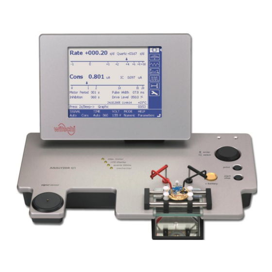
Page 8: Display Panel
An information line under the result field contains information on the current measurement 4 COMMISSIONING 4.1 Extent of Delivery The basic equipment comprises the following components: Test instrument ANALYZER Q1. Mains adapter 230 V~ or 120 V~. 2 cables with probe tips. Pair of movable contact probes. -
Page 9: Place Of Installation
4.3 Mains Connection A mains adapter supplies ANALYZER Q1 with a 9 V~ output alternating voltage and a 1.2 A output current. The mains adapter can be provided for a 230 V~ mains voltage (from 210 V~ to 240 V~) or a 120 V~ mains voltage (from 110 V~ to 130 V~). -
Page 10: General Operation
5 GENERAL OPERATION 5.1 Switching the Analyzer Q1 On and Off The mains switch for switching the instrument on and off is located on its rear panel. Whenever the instrument has been switched on, the following information appears during the... -
Page 11: Parameter Settings
After a measurement function has been selected, all parameters are set to the most commonly preferred values. Modified parameters are reset to the preferred values when the measurement function is exited. Witschi Electronic Ltd Analyzer Q1 Page 11... -
Page 12: Help
HELP Select parameter and press the rotary knob. Parameters Results Select according to the information desired. Press the rotary knob once more to go back to measurement. Page 12 Analyzer Q1 Witschi Electronic Ltd... -
Page 13: Rate Measurement Of Quartz Watches
The Analyzer Q1 is equipped with a single transducer for acoustic, capacitive and magnetic signal acquisition. It allows checking watches with closed wristlet, open watches and movements. If the watch is supplied from the Analyzer Q1, its rate deviation is derived from the supply current (see chapter 9.2). -
Page 14: Result Display
If the signal is no longer available, the indication appears and the instrument jumps to the main menu after a while. Caution! If a watch is supplied from the Analyzer Q1, it is not possible to test another watch with the sensor. 6.3 Result Display Numeric mode, the current results are displayed in numerical and graphical analogue form. -
Page 15: Pulse Parameters
60h. 8.1 Result Display The upper part of the display contains the rate measurement diagram and the lower part the power level of the chopping pulses. Witschi Electronic Ltd Analyzer Q1 Page 15... -
Page 16: Module Supply And Current Measurement
The mirror underneath the support allows you to watch the hands of the watch. If the watch is running, the contacts have been correctly set up. The consumption and rate measurement starts automatically from the main menu as soon as the instrument detects a current. Page 16 Analyzer Q1 Witschi Electronic Ltd... -
Page 17: Current Measurement
(measuring time 480 / 960 seconds). spike Analyzer Q1/Twin controls the filter function by a variable supply voltage of 1.55V to 3.50V Graphical representation of the trigger (spike-filter) operation:... -
Page 18: Minimum Operating Voltage
9.3 Minimum Operating Voltage The minimum operating voltage supplies information on the power reserve of the watch and its capability to function even with a nearly exhausted or strongly stressed battery. The correct Page 18 Analyzer Q1 Witschi Electronic Ltd... -
Page 19: Watch Acceleration
A load of 2 kΩ is switched on once per second for 10ms; it simulates the step motor. The voltage Low Drain associated to this load ( ) is continuously determined and displayed. Witschi Electronic Ltd Analyzer Q1 Page 19... -
Page 20: Result Display
11 GRAPH OF THE MOTOR PULSE 11.1 General Introduction The Analyzer Q1 can record the motor current pulse as an oscillogram. In addition to the pulse parameters, the shape of the current pulse provides additional information on the state of the watch. -
Page 21: Result Display
If the measuring points cannot be located, refer to the data sheet of the module to be tested. Coil insulation Connect the movable contact probes or the probe tips to a wiring point of the coil and to the movement plate. Witschi Electronic Ltd Analyzer Q1 Page 21... -
Page 22: Result Display
- Select the pulse width ( ) and the chopping level ( ) according to the data needed for testing the watch. FREQ For an acceleration test, select the 16 Hz pulse frequency under Page 22 Analyzer Q1 Witschi Electronic Ltd... -
Page 23: Buzzer Test
14 BUZZER TEST 14.1 Field of Application The Analyzer Q1 can also test acoustic alarm transmitters of alarm watches. The instrument provides a bipolar test signal with adjustable voltage and a fixed frequency of 2 kHz. 14.2 Procedure It is necessary to remove the battery from the watch to test the buzzer. -
Page 24: Testing Mechanical Watches
15 TESTING MECHANICAL WATCHES 15.1 General Introduction The Analyzer Q1 can measure the rate and the beat error (Repère) of mechanical watches. Vario display mode also includes the maximum and minimum measurement values as well as the average rate deviation for the entire measurement time. -
Page 25: Long-Time Recording
The magnetic stray field or the current pulses of the step motor, the capacitive stray field of the LCD display, the electrical stray field or the mechanical oscillations of the quartz oscillator are used, depending on the measuring mode. Witschi Electronic Ltd Analyzer Q1 Page 25... - Page 26 16.1.3 Motor Current Signal Source This test mode is used for quartz watches with a step motor that are supplied from the Analyzer Q1. Based on the current pulses, the instrument determines the rate deviation as well as the pulse...
- Page 27 The quartz frequency is derived from the supply current if the Analyzer Q1 is supplying the watch. The switching to the suitable signal recording occurs automatically.
-
Page 28: Watches With Inhibition Compensation
For that reason, the instrument displays the current ambient temperature that will also appear in the measurement log printout. The measurement accuracy of the Analyzer Q1 is not influenced by fluctuations of the ambient temperature. 16.4 Typical Values of the Rate Deviation The compensation in inhibition-compensated watches is mostly performed in steps of 0.18 s/d (also... -
Page 29: Motor Pulse Analysis
The consumption increases in the case of shocks, of change of date, of sinking battery voltage, but also of mechanical faults. The Analyzer Q1 allows for the first time to test the chopping level, hence the power level, of closed watches. -
Page 30: End Of Life (Eol) Function
(typical 1.25 V). The correct operation of this display can be tested by decreasing the voltage. Keep in mind the fact that the EOL function does not react immediately to a voltage change. In most cases, the module only tests the battery voltage once a minute. Page 30 Analyzer Q1 Witschi Electronic Ltd... -
Page 31: Battery Testing
As there are several technologies and application classes of lithium batteries, it is impossible to make general statements. The following values can be considered as typical values: No Load Low Drain voltage Good battery: 2.9 – 3.2 V End of lifetime: below 2.8 V Witschi Electronic Ltd Analyzer Q1 Page 31... -
Page 32: System Parameters
17.2 TYPE General TIME You can set up and correct the time of the built-in clock. If the Witschi GPS receiver is connected, you can only adjust the Hour (in accordance with the time zone). The GPS receiver automatically sets and synchronises minutes and seconds. - Page 33 When this function is activated, a short beep sounds during the last five seconds of every minute. This function can be used for setting a watch. BEEP – TEST END A beep sounds when this function is activated whenever a new result appears during a long measurement time. Witschi Electronic Ltd Analyzer Q1 Page 33...
-
Page 34: Type Interfaces Printer
The header is not printed HEADER The device as delivered displays the following text: Witschi Electronic AG ANALYZER Q1 You can edit without restriction the two 22-character lines according to your requirements and replace them with your own information. Procedure: ... -
Page 35: Type Info
The interface is deactivated; data are not sent to the printer. GPS RTC If the Witschi GPS receiver (available as an accessory) is connected, the minutes and seconds of the watch are automatically synchronised. The real time clock (Real Time Clock) is not synchronised. -
Page 36: Connection To A Pc
18.2 Installation printer Switch off the Analyzer Q1 and the PC before interconnecting them. Connect the RS232 interface of the instrument with the 9-pin link cable to the COM1 or COM2 port of the PC. The installation and operating instructions are available in the Autoprint Instruction Manual. - Page 37 Instantaneous current value during a measurement time of 2 s (independent of the measurement time selected). Display range 20 µA, logarithmic scale. Fault displays: Acoustic signal and “out of measurement range” display when the current >20 mA. Witschi Electronic Ltd Analyzer Q1 Page 37...
- Page 38 Bipolar motor pulses (the selected pulse shape is displayed as an oscillogram). Pulse width: Programmable 2.94 - 31.25 ms in steps of 0.49 resp. 0.98 ms. Repetition frequency: Programmable 1, 2, 4, 8, 16, 32 Hz. Page 38 Analyzer Q1 Witschi Electronic Ltd...
-
Page 39: Additional Functions
10° - 40° ± 0.004 s/24h. Aging after one year: less than ± 0.03 s/24h. Optional synchronisation with GPS receiver (option) Accuracy: ± 0.001 s/24h. No influence on accuracy from aging or temperature. Witschi Electronic Ltd Analyzer Q1 Page 39... -
Page 40: Accessories
Thermo printer with cutter (100-240V~) Item No. JB01-SLK-TE25-S Thermo paper: roll Item No. JA01-MM60-740RS Witschi GPS receiver, allowing synchronisation of time base Item No. 19.91PK1 and real time clock. Autoprint: PC software for data transfer Item No. 64.55.901PK1 incl.
Need help?
Do you have a question about the ANALYZER Q1 and is the answer not in the manual?
Questions and answers