Advertisement
Quick Links
Installation Guide, Parts List & Maintenance
Parts List:
Keypad
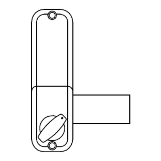
Inside Lock Body
Neoprene Seals x 2
Mortised Lock Keep
Surface Lock Keep x 2
Morticed Lock Keep
BL2605MG
Instructions
Fixing Bolts (6 supplied)
Use only 2 depending on gate thickness. See table 4A
Factory Pre-set Code
Card
Wood Screws x 8
Wood Screws x 4
Tweezers x 1
80 mm x 2 (3 1/8")
70 mm x 1 (2 ¾")
60 mm x 1 (2 3/8")
50 mm x 1 (2")
40 mm x 1 (1 ½")
Hexagonal shaft x 2
2 3/8" (60mm)
Spare Tumblers
2 x coded
2 x blank
Spindle/ Key Stock x 3
135 mm x 1 (5 5/16")
160 mm x 1 (6 5/16")
135mm x 1 (5 5/16")
1
Advertisement

Related Manuals for Borglocks BL2605MG

Summary of Contents for Borglocks BL2605MG
- Page 1 BL2605MG Installation Guide, Parts List & Maintenance Instructions Parts List: Factory Pre-set Code Card Wood Screws x 8 Wood Screws x 4 Tweezers x 1 Fixing Bolts (6 supplied) Keypad Inside Lock Body Use only 2 depending on gate thickness. See table 4A 80 mm x 2 (3 1/8”)
- Page 2 Before commencing installation , check that all parts are working correctly. Press the code into the lock, as per the code card provided and then turn the knob it should turn easily under spring pressure. If you intend to change the code, this should be done before installing the lock, see “How to Change your Code”. How to Change Your Code: The C button must be held down during recoding process Before installing the lock, or Remove the lock from the door 1.
- Page 3 Determining your Gate Handing (Table 3A) Right Hand installation shown below FLUSH ON THE OUTSIDE FLUSH ON THE INSIDE INSTALLED IN CENTER OF OPENING Changing the Handing of Lock (Table 4A) Installation Exploded View (Table 5A)
- Page 4 Installation instructions: Using Diagram 3 determine which hand (left or right) lock you require for your specific application. Using table 2A determine the length of the machine screws, hexagonal shaft and key stock spindle configuration required for your gate or door thickness. This lock comes equipped to fit up to a 4 1/4” thick gate or door. Using a hack saw cut the key stock spindle 1 5/8”...
Need help?
Do you have a question about the BL2605MG and is the answer not in the manual?
Questions and answers