Advertisement
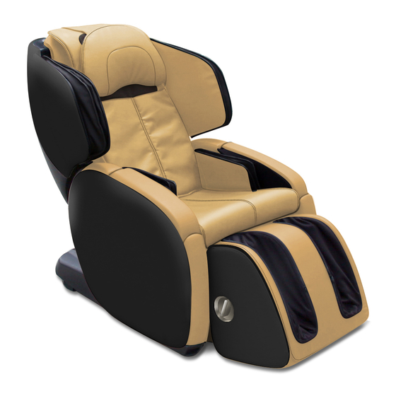
AcuTouch
It is imperative that Human Touch
products are repaired in a manner that ensures product safety and regulatory compliance and that is fully consistent with the practices used
®
during the manufacturing process. Therefore, Human Touch requires that all product repairs are performed using only factory-new parts and in accordance with these repair
instructions. Failure to adhere to these instructions voids the product warranty and releases Human Touch from all liability for injury or product damage resulting from the repair.
Tools Required: Phillips-head screwdriver, wire cutter or any other instrument suitable for
cutting zip ties, paper clip.
NOTE: SAVE ALL REMOVED PARTS FOR USE DURING REASSEMBLY
REMOVING THE BACKREST ACTUATOR
1. Power off the chair and unplug it.
2. Using a Phillips-head screwdriver, remove the two screws from the safety sensor plate
on the back of the chair (Fig.1).
3. Pull the safety sensor cover backward to expose the zipper that connects the safety
sensor cover to the chair (Fig.2).
4. Using a paper clip, open the zipper, then remove the safety sensor cover (Fig.2).
5. Carefully lift the safety sensor cover away from the chair (Fig.3).
Safety sensor
cover
(Fig.1)
6.0
®
Zipper
Safety sensor
cover
(Fig.2)
REPLACING THE MAIN PCB
April 04, 2012
SERVICE LEVEL: 3
Main PCB
Safety sensor
cover
(Fig.3)
1
Advertisement
Table of Contents

Summary of Contents for Human Touch AcuTouch 6.0
- Page 1 SERVICE LEVEL: 3 instructions. Failure to adhere to these instructions voids the product warranty and releases Human Touch from all liability for injury or product damage resulting from the repair. Tools Required: Phillips-head screwdriver, wire cutter or any other instrument suitable for cutting zip ties, paper clip.
- Page 2 6. Using a wire cutter, cut all of the zip ties that secure the Main PCB cable harnesses. 7. Disconnect the 24 connectors from the Main PCB (Fig.4). 8. Disconnect the connector from the safety sensor (Fig.5). 9. Using a Phillips-head screwdriver, remove ten screws from the center of the Main PCB, which secures the PCB to the chair (Fig.5). 10.
- Page 3 7. Secure the safety sensor cover using two screws. 8. Plug in the chair and power it on, then verify that all the functions are functioning are now working properly. Please send any questions or comments regarding these instructions to: documentation@humantouch.com © 2012 Human Touch , LLC. ®...


Need help?
Do you have a question about the AcuTouch 6.0 and is the answer not in the manual?
Questions and answers