Table of Contents
Advertisement
All information, including illustrations, is believed to be reliable. Users, however, should independently
evaluate the suitability of each product for their application. Raychem makes no warranties as to the
accuracy or completeness of the information, and disclaims any liability regarding its use. Raychem's only
obligations are those in the Raychem Standard Terms and Conditions of Sale for this product, and in no
case will Raychem be liable for any incidental, indirect, or consequential damages arising from the sale,
resale, use, or misuse of the product. Specifications are subject to change without notice. In addition,
Raychem reserves the right to make changes—without notification to Buyer—to materials or processing
that do not affect compliance with any applicable specifications.
R
Belgium
NV Raychem SA
Diestsesteenweg 692
3010 Kessel-Lo
Tel (32) 16/351-800
Fax (32) 16/351-797
Korea
Raychem Korea Limited
831-45 Yeuksam-Dong
Kangnam-Ku
Seoul 135-080
Tel (82) 2/ 3468-1300
Fax (82) 2/ 558-5765
United Kingdom
Raychem Ltd.
Faraday Road
Dorcan, Wiltshire SN3 5HH
Tel (44) 1793/ 572-663
Fax (44) 1793/ 572-189
United States
Raychem Corporation
300 Constitution Drive
Menlo Park, CA 94025-1164
Tel (800) 553-1737
(415) 361-4900
Fax (415) 361-3215
R
TraceTek
Long-Line and Zone
Leak Detection and Location Systems
Operation and Maintenance Manual
For TTDM-1, TTDM-2, and TTDM-24
Alarm and Locating Modules
Advertisement
Table of Contents

Related Manuals for Raychem TraceTek TTDM-2


Summary of Contents for Raychem TraceTek TTDM-2
- Page 1 Raychem’s only obligations are those in the Raychem Standard Terms and Conditions of Sale for this product, and in no case will Raychem be liable for any incidental, indirect, or consequential damages arising from the sale, resale, use, or misuse of the product.
-
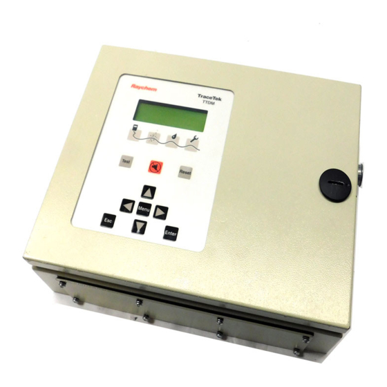
Page 2: Identifying Ttdm Features
Identifying TTDM Features External View [A] Internal View [B] TraceTek TTDM (1) LCD display gives up-to-date (7) User interface board information regarding the condition of the system. (8) 4–20 mA board (2) Icons and LEDs (light emitting (9) Sensor interface board diodes): Monitoring LED green... -
Page 3: Table Of Contents
Introduction Contents Please read before use Identifying TTDM Features ..........ii Please read these instructions carefully and keep in a safe place (preferably close to the Introduction . -
Page 4: Leak Detection System Description
Leak Detection System Description The TraceTek Zone System TraceTek Longline System The TraceTek zone system is a leak detection and location system that monitors many A TraceTek longline system provides distributed leak detection and location to monitor separate locations from one point. The zone system consists of the TTDM Alarm and long lengths and wide areas. -
Page 5: Connection To Other Devices
Connection to Other Devices Serial Port Relays The TTDM module has a serial port (marked EXT COM PORT) that can be configured for TTDM has three relays: use either as an RS-232 or RS-485 transceiver. The factory default is RS-232, and is •... -
Page 6: The Basic Events
The Basic Events Leak The Icons The Icons (2 on foldout) represent the four main states of the TTDM module: When liquid is detected on the sensing cable, this red Leak LED illuminates. Note that the Green Yellow green LED remains illuminated; the unit continues to monitor for leaks and spills. This is cov- ered more fully in the following section “Leak Detection and Location Events”, on page 8. - Page 7 Leak Detection and Location Events To Locate the Leak If the TTDM unit has been installed correctly, and the system is clear, the LCD display will appear as follows: Using the number displayed by the TTDM, refer to the system map and determine where the leak was detected.
-
Page 8: Service Events
Service Events The number in square brackets indicates the estimated location of the material causing Introduction the alarm. The number is shown with square brackets to indicate that the value is only an A TraceTek sensing circuit consists of two electrical loops (a diagram of the sensing estimate. -
Page 9: Fault Events
Fault Events To Remedy the Problem Introduction Find the problem and rectify. This may mean reconnecting the cable, or finding the dam- Several conditions could lead to a fault alarm: aged section and replacing it. If the cause of the fault is not obvious by visual inspection, •... -
Page 10: Multiple Events
Multiple Events Example (continued): In addition to storing all events in memory, TTDM gives a direct indication of multiple events, that is, events which happen after an initial leak but before the module is manually Before the problem can be dealt with, the leak spreads. Once the module has detected reset. - Page 11 Note how this leak event differs from the simpler leak event detailed on page 8: Additional Leak • Rather than displaying the message “Leak 50 ft,” the display puts the location in square If liquid contacts the sensing cable away from the initial leak, the module will re-alarm. If brackets.
-
Page 12: Navigating The Menu Structure
The TTDM can store up to 512 events. If 512 events are already stored, the oldest event is discarded as a new event is registered. When this has occurred, the Events History leaves the bottom line of the display blank. Contact Raychem for assistance if you wish to clear the event history. -
Page 13: Diagnostics (System Status)
Diagnostics (System Status) Location System Status The current location—or electrical center—of the leak (or cause of a Service alarm). If the System Status provides a real-time view of the system. You gain access to this feature status is System Normal, the Location entry is blank. through the main menu. -
Page 14: Changing Settings (View/Edit Settings)
Changing Settings (View/Edit Settings) Language You gain access to the system’s settings through the View/Edit Settings Menu, which is on the main menu (see “Appendix 1 - “Menu Structure” on page 25). Four types of set- Select from available options (English, Français,...) tings are available: Change Password •... -
Page 15: Appendix 1 - Menu Structure
If you are using a zener barrier (or a lightning protection device) its resistance can be “dialed out” so the system map can begin at 0. Note: Always set this value BEFORE mapping the system. Consult your Raychem TraceTek representative for further details. -
Page 16: Appendix 2 - Events Glossary
Appendix 2 - Events Glossary SI H/W Error A self-test of the Sensor Interface Hardware has Type of failed; the unit needs repair. Event Message Description SI H/W Recovered The hardware problem has been corrected. Power Power Down The time power was last supplied is stored in nonvolatile memory, and is entered into the Service Service Req’d... -
Page 17: Appendix 3 - Maintenance
Contact your local Raychem TraceTek representative for further information on service support. Storage and Handling of Sensing Cable... -
Page 18: Appendix 4 - Interface Details
“4–20 mA Test” series under the Self-Test Menu. Before Contact your Raychem TraceTek representative for additional information to assist in con- doing so, confirm that all connections have been made, including 24 Vdc to TTDM necting and configuring for serial port communications. -
Page 19: Appendix 5 - Wiring Details
Appendix 5 - Wiring Details Appendix 6 - TraceTek Technical Data TTDM Operation Diagram Relay wiring options The illustrations below show how relays (15, 16, and 17 on foldout) can be jumpered together to allow remote monitoring of the TTDM status with only a single pair of wires. Loop resistances and test length The TTDM de-energizes its relays to signal an alarm condition.
Need help?
Do you have a question about the TraceTek TTDM-2 and is the answer not in the manual?
Questions and answers