ABB RMC-100 Startup Manual
Remote modular controller
Hide thumbs
Also See for RMC-100:
- Quick start manual (2 pages) ,
- Startup manual (40 pages) ,
- User manual (215 pages)
Table of Contents
Advertisement
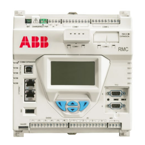
Startup guide
Remote Modular Controller
RMC-100
A scalable controller supporting control and
measurement applications from simple to
large oil and gas production and
transmission sites
Introduction
The startup guide is designed for typical installations only. Installations must be performed
by personnel knowledgeable of the Remote Modular Controller 100, local and national
codes, communication wiring, and electrical wiring. Many sites have unique system
installation requirements. In these cases it is important to reference site-specific
documentation.
In this startup guide, the Remote Modular Controller 100 will be referred to as the RMC or
the controller, unless otherwise indicated.
WARNING – Bodily injury/ equipment damage. Although there may
be alternate methods of installation and commissioning of the RMC, it
is recommended that technicians perform the procedures in the
presented order: plan, install, wire before applying power, apply power,
verify power-on sequence, and configure.
WARNING – Bodily injury. The RMC-100 startup guide does not
address any requirements for the installation of product(s) in hazardous
(classified) locations. Refer to the installation instructions and local and
national electrical codes for installation requirements in hazardous
(classified) locations.
Advertisement
Table of Contents

Related Manuals for ABB RMC-100


Summary of Contents for ABB RMC-100
- Page 1 WARNING – Bodily injury. The RMC-100 startup guide does not address any requirements for the installation of product(s) in hazardous (classified) locations. Refer to the installation instructions and local and national electrical codes for installation requirements in hazardous (classified) locations.
-
Page 2: Additional Information
ABB Inc. and its affiliates are not liable for damages and/or losses related to such security breaches, any unauthorized access, interference, intrusion, leakage and/or theft of data or information. -
Page 3: Health And Safety
1 Health and safety Safety warning and note conventions DANGER – Serious damage to health / risk to life. This symbol, in conjunction with the signal word "DANGER", indicates an imminent electrical hazard. Failure to observe this safety information will result in death or severe injury. -
Page 4: Site Planning And Requirements
— Enclosure must protect the RMC-100 against shock and impact. — For Class I, Division 2, or other outdoor installations, the RMC-100 shall be installed in an enclosure rated at least Type 3R, according to the environment. — For Class I, Zone 2 installations, the RMC-100 shall be installed inside an enclosure tested for IP54 in accordance with IEC 60529 and IEC 60079-15. -
Page 5: External Power Supply Requirements
External power supply requirements When powering the controller with external power (EXT PWR mode), comply with the following specifications: — Power supply must be rated as a NEC Class 2 power source. EXT PWR mode operation is +9 Vdc to 30 Vdc, 5A maximum. RMC rating for ambient temperature without battery is Ta = -40 °C to +70 –... -
Page 6: Basic Hardware Installation
4 Basic hardware installation This is an overview of basic hardware installation. For different installations, refer to the user manual or call the ABB main office number listed on the back page of this guide. WARNING – Equipment damage. It is recommended that technicians perform all of the procedures in the order presented in this section before powering the RMC. - Page 7 Mounting the RMC To mount the controller on the DIN rail: Position the RMC on the DIN rail. Push the RMC onto the DIN rail until it snaps into place (Figure 1). CO MM E X P A N SIO N Figure 1: Mounting the RMC IMPORTANT NOTE.
- Page 8 Table 2 identifies RS-232, RS-422, and RS-485 communication pinouts for COMM 1 and COMM 2. Table 2: COMM 1 and COMM 2 serial communication pinouts RS-232 RS-422 RS-485 Voltage Out (VOUT) Voltage Out (VOUT) Voltage Out (VOUT) Ground (GND) Ground (GND) Ground (GND) Switched voltage Switched voltage...
- Page 9 Insert the communication module in the appropriate slot (Figure 2). The communication module pushes the port cover downward when inserted. COMM 1 COMM 2 BAT CHARGER/EXT PWR RMCIO EXPANSION COMM 1 COMM 2 Figure 2: COMM terminals and modules Wiring I/O ports Wire the RMC I/O ports to monitor, control and power external devices.
-
Page 10: Analog Output Pinouts
4.4.1 Analog input pinouts Table 3 and Figure 3 identify the AI pinouts. CAUTION – Equipment damage. Before connecting to pin 1 (PWR), ensure that the external device is compatible with the input voltage at the CHARGER/EXT PWR port. Connecting an incompatible device may result in damage to the device. - Page 11 4.4.3 Pulse input pinouts Table 5 and Figure 5 identify the PI pinouts. Table 5: Pulse input pinouts Input Description INP - Pulse input 1 GND - Ground INP - Pulse input 2 GND - Ground Figure 5: Pulse input pinouts 4.4.4 Digital input and output pinouts Table 6 and Figure 6 identify the DI/DO pinouts.
- Page 12 Table 7 identifies the different module types available that support 9 to 30 V operation. RMC does not support the TFIO CIM module, part number 2100421. Table 7: TFIO modules TFIO module Part number TFIO software version Valve Control Combo I/O (M2) 2100412 2100576-007 4–20 mA Analog Output (M2)
- Page 13 Figure 7 shows the side view of a TFIO module and its pinouts. Pins Side View Figure 7: TFIO module Table 8 to 13 identify the wiring pins for the TFIO M2 modules used with the RMC. The wiring pins are the same for legacy TFIO modules. CAUTION –...
- Page 14 Table 10: TFIO analog input module (M2) AI1 (+) AI3 (+) AI5 (+) AI7 (+) AI1 (GND) AI3 (GND) AI5 (GND) AI7 (GND) AI2 (+) AI4 (+) AI6 (+) AI8 (+) AI2 (GND) AI4 (GND) AI6 (GND) AI8 (GND) Table 11: TFIO combo digital module and extended (M2) POINT 1 SIG POINT 3 SIG POINT 5 SIG...
-
Page 15: Power-On Sequence
LCD as the controller completes its startup: — ABB TOTALFLOW RMC-100 – identifies the controller name and model — BOOT 2105412-XXX – indicates the version of the boot software — OS 2105411-XXX – indicates the version of the operating system —... -
Page 16: Connecting The Charger
WARNING – Bodily injury and property damage. Do not allow the battery terminals or cable ends if attached, to come in contact with any metal surface. When the positive and negative battery terminals contact a conductive material, this creates a short circuit and could result in sparks, property damage, and possible explosion. - Page 17 If the measured voltage is out of specification, call the ABB main office number listed on the back page of this guide for a replacement panel. Connect the solar panel cable to the CHARGER/EXT PWR terminals as shown in Figure 9.
-
Page 18: Lithium Battery
Powering with external power The controller can be powered from an external power supply (9 to 30 Vdc). IMPORTANT NOTE: Make sure that the external power supply meets the specifications in section 2.3, External power supply requirements. WARNING – Equipment damage. A battery cannot be used when the controller is in the EXT PWR mode. - Page 19 Disable - The switch is off. The lithium battery does not back up the real time clock. To ensure the lithium battery is enabled, insert a small screwdriver in the slot and move the switch to the ENABLE position as shown in Figure 11. TFIO cover RESET LITH...
- Page 20 On the PCCU32 tool bar, click Setup. The System Setup window displays (Figure 12). Figure 12: System setup Under Communications in the Setup tab, click the Serial port radio button. Select the PCCU Com. Port from the drop-down list (the computer USB port that the cable is connected to).
-
Page 21: Configuring The Station
Configuring the station To configure the station: At the PCCU32 Entry screen, click the station ID name in the top node of the navigation tree. The Station Setup tab displays. Set up the basic settings identified in Table 14. Table 14: Required Station setup Entry Format Description... - Page 22 IMPORTANT NOTE: The codes will be required the next time PCCU32 attempts to connect to the RMC. Call the ABB main office number listed on the back page of this guide if you need further assistance with security. 22 | 2105551-001 rev. AC...
-
Page 23: Configuring Communications
Changing the LCD display The factory configuration has a default date and time display. To change the display to preferred settings: On the Station Setup tab, scroll down to the LCD Display Date/Time Format section (Figure 16). Figure 16: LCD display date and time format Select the preferred Date/Time Format (mmddyy or yymmdd). - Page 24 Select the appropriate application from the Select Application drop-down list. IMPORTANT NOTE: Some of the applications in the list are designed for specific ABB products. If the external device is not an ABB product, select Generic Com App. Select the appropriate protocol from the Select Protocol drop-down list.
- Page 25 Figure 19 provides a communication configuration example to connect an ABB Totalflow product, such as a multivariable transmitter or XMV. The XMV Interface is chosen to support this type of connection. Figure 19: Serial port configuration to connect XMVs Figure 20 provides a communication configuration example to connect equipment for remote communication such as a radio.
-
Page 26: Configuring Ethernet Communication
Third party serial-to-Ethernet modules can be used to add serial communication ports for external devices such as XMVs and transmitters. The configuration instructions are provided from the manufacturer. Refer to the RMC-100 User Manual for the configuration of the RMC to support third party devices. -
Page 27: Analog Input Configuration
To reflect the external device's AI value range in non-default engineering units, the AI must be calibrated. For AI calibration, refer to the RMC-100 User Manual. Analog inputs can be configured for voltage or current input signals. Choose the signal type that matches that of the external device. -
Page 28: Analog Output Configuration
Engineering units defined on the calibration screen are automatically reflected in the Analog Output tab (Figure 24).screen. For AO calibration, refer to the RMC-100 User Manual. If you need to change settings for the analog output after the first time calibration: Select I/O System on the navigation tree. -
Page 29: Pulse Input Configuration
Select the Type from the drop-down list. Digital Input (Voltage) is the default. Configure each Digital I/O port as appropriate: For digital input mode, select the low and high threshold voltage. For digital output mode, select the current value and the initial value. Click Send. - Page 30 9 Configuring TFIO interfaces To scan and transmit data using the TFIO modules, the RMC TFIO interface must be enabled. Connected TFIO modules are detected only when the interfaces are enabled. IMPORTANT NOTE: The TFIO-A interface is enabled by default. The TFIO-B is disabled by default.
-
Page 31: Troubleshooting
10 Troubleshooting 10.1 Visual alarm and status codes After powering on, observe the LCD display. System alarms may display and indicate a condition to be resolved (Figure 28). DATE/TIME 02/28/16 13:00:26 Annunciators Figure 28: LCD display Table 15 provides a description of the alarms and status codes. The alarms provide a brief summary of the action to resolve the condition. -
Page 32: Additional Assistance
Local terminal protocol or TESORO tank gauge ADP protocol Bluetooth listen Network listen ScaData protocol X-Frame host annunciator 10.2 Additional assistance For assistance, call the ABB main office number listed on the back page of this guide. 32 | 2105551-001 rev. AC... - Page 33 Notes 2105551-001 rev. AC | 33...
- Page 34 This page left intentionally blank 34 | 2105551-001 rev. AC...
- Page 35 This page left intentionally blank 2105551-001 rev. AC | 35...
- Page 36 +1 918 338 4699 maintained as accurately as possible. Should any discrepancies exist, the US English version will be considered final. ABB is not liable for any errors and omissions in the translated materials. Any and ABB Inc. all derivatives of, including translations thereof, Measurement &...
Need help?
Do you have a question about the RMC-100 and is the answer not in the manual?
Questions and answers