ABB RMC-100 Startup Manual
Remote modular controller
Hide thumbs
Also See for RMC-100:
- Startup manual (37 pages) ,
- Quick start manual (2 pages) ,
- User manual (215 pages)
Table of Contents
Advertisement
Quick Links
Advertisement
Table of Contents

Related Manuals for ABB RMC-100


Summary of Contents for ABB RMC-100
- Page 1 — ABB ME A SUR E ME NT & AN A LYT IC S | 2 105 551 MN AD Remote Modular Controller (RMC-100) Startup Guide A scalable controller supporting control and measurement applications from simple to large oil and gas production and...
-
Page 2: Table Of Contents
— Contents Contents ........................... 2 List of figures ........................... 3 List of tables ..........................4 Additional information ......................5 Compliance ..........................6 Cyber security ......................... 6 Waste Electrical and Electronic Equipment (WEEE) ............... 6 Safety ............................7 Safety symbol conventions ......................7 Potential safety hazards ...................... -
Page 3: List Of Figures
Analog output configuration .................... 31 Digital input/digital output configuration ................32 Pulse input configuration ....................32 Expand I/O capacity with the ABB XIO ................33 9 Configure directly attached TFIO interfaces ............... 33 10 Enable for MQTT support ....................36 11 Troubleshooting ......................... -
Page 4: List Of Tables
Figure 9-4: TFIO-B Module Setup ....................35 Figure 9-5: TFIO-B Module List ....................36 Figure 10-1: RMC-100 Services ....................37 Figure 10-2: Enable MQTT Service and REST Service on the RMC-100 ..........37 Figure 11-1: LCD display ......................38 List of tables Table 0-1: Related documentation .................... -
Page 5: Additional Information
Additional information Carefully read the contents of this startup guide prior to beginning installation. For any questions that are not answered in this guide, or in the documentation listed below, call the ABB main office number on the last page. -
Page 6: Compliance
Compliance Cyber security This product is designed to be connected, and communicate information and data, via a network interface. All ABB Totalflow products should be connected to a secure network. It is the customer's sole responsibility to provide, and continuously... -
Page 7: Safety
The content of these instructions is neither part of nor provided for changing a previous or existing agreement, promise, or legal relationship. All obligations of ABB result from the respective sales contract, which also contains the full and solely valid warranty clauses. These are neither limited nor extended by the content of these instructions. -
Page 8: Potential Safety Hazards
Do not separate components when energized. This applies to all connectors and connections, cabling and wiring. WARNING – Bodily injury. The RMC-100 startup guide does not address any requirements for the installation of product(s) in hazardous (classified) locations. Refer to the installation instructions and local and national electrical codes for installation requirements in hazardous (classified) locations. -
Page 9: Introduction
The RMC must be installed in an enclosure complying with the following specifications: Enclosure must protect the RMC-100 against shock and impact. For Class I, Division 2, or other outdoor installations, the RMC-100 shall be installed in an enclosure rated at least Type 3R, according to the environment. -
Page 10: Location Specifications And Design
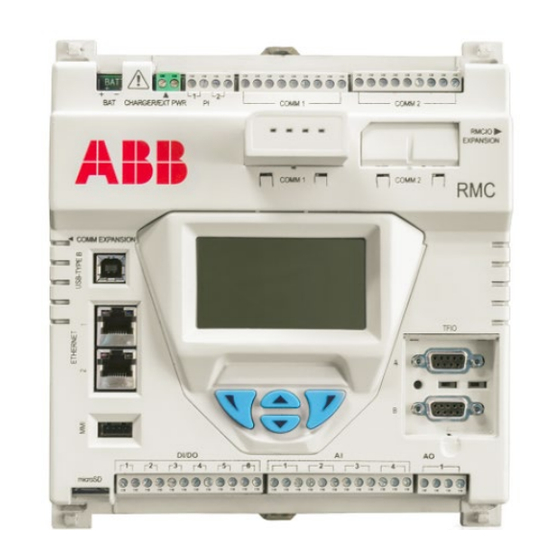
RMC exterior LCD display Optional equipment if purchased If there are any missing, incorrect, or damaged parts or noticeable defects, call the ABB main office number listed on the last page of this guide. Basic hardware installation This is an overview of basic hardware installation. -
Page 11: Ground The Controller
Ground the controller The RMC must be grounded by mounting on a grounded DIN rail. NOTICE – Equipment damage. The DIN rail on which the controller is mounted must be bonded to an earthing terminal. The bonding conductor must have a cross sectional area of at least 12 AWG or 4 mm To ground the DIN rail: Screw the DIN rail onto the mounting surface. -
Page 12: Wire I/O Ports
RS-232 RS-422 RS-485 Operate (OPER) Operate (OPER) Operate (OPER) Remote request to send (RRTS) Remote request to send (RRTS) Remote request to send (RRTS) Request to send (RTS) Transmit bus+ (TBUS+) Transmit/Receive (BUS+) Transmit data (TX) Transmit bus- (TBUS-) Transmit/Receive (BUS-) Receive data (RX) Receive bus+ (RBUS+) Not Used... -
Page 13: Analog Input Pinouts
Before connecting to these pins, ensure that the external device is compatible with the input voltage at the CHARGER/EXT PWR port. Connecting an incompatible device may result in damage to the device. Use a slotted screwdriver to pry the terminal connector off the electronic board. Trim the wire covering back ¼... -
Page 14: Pulse Input Pinouts
Table 4-4: Analog output pinouts Output Description PWR - Loop power input SNK - Current sink input SRC - Current source output GND - Ground Figure 4-4: Analog output pinouts 4.4.3 Pulse input pinouts Table 4-5 Figure 4-5 identify the PI pinouts. Table 4-5: Pulse input pinouts Input Description... -
Page 15: Connect Tfio Modules
Connect TFIO modules The RMC has two TFIO ports. Each TFIO port requires a TFIO installation kit which includes the cable to connect the TFIO modules to the RMC. For additional information, refer to the TFIO Module User Manual. See Additional NOTICE –... -
Page 16: Figure 4-7: Tfio Module
NOTICE – Equipment damage. Do not overtighten the terminal connector screws as this may damage the wire. Figure 4-7 shows the side view of a TFIO module and its pinouts. Figure 4-7: TFIO module Pins Side View Table 4-8 through Table 4-13 identify the wiring pins for the TFIO modules used with the RMC. -
Page 17: Power The Rmc
The RMC power on sequence is initiated as soon as power is connected. The following information may be displayed on the LCD as the controller completes its startup: ABB TOTALFLOW RMC-100: identifies the controller name and model BOOT 2105412-XXX: indicates the version of the boot software ... -
Page 18: Super Capacitor
The RMC may use a solar panel (20 Watt or less) with Nominal 12 Vdc output voltage. The solar panel may be mounted on a 2 inch pipe or the top or side of a meter house. Call the ABB main office number... -
Page 19: Power With External Power
If the measured output voltage is within the manufacturer’s specification as defined by the specification sheet supplied with the panel, continue with the installation. If the measured voltage is out of specification, call the ABB main office number listed on the last page of this guide for a replacement panel. -
Page 20: Lithium Battery
Establish local communication Establish initial communication with the RMC-100 with a direct connection to the USB or Ethernet ports. Local connection on USB Local communication between a host system (laptop or PC) and the RMC can be established by a direct USB connection. -
Page 21: Local Connection On Ethernet
To set up local communication using the USB port: Power on the RMC and laptop. Connect the USB cable. An annunciator in the RMC LCD displays a lower case “u” for local USB connection. On the laptop start PCCU. On the PCCU32 tool bar, click Setup. The System Setup window displays (Figure 6-1). -
Page 22: Figure 6-3: Factory Default Ethernet Configuration
Figure 6-3: Factory default Ethernet configuration To establish local connection: Connect the laptop to either Ethernet port. Start PCCU32. Click the Setup icon on the PCCU32 toolbar menu. The System Setup window displays. Under Communications, select TCP/IP. Under Connection Parameters, type the IP address: 169.254.0.11. 22 | RM C-100 | 2105551MN AD... -
Page 23: Configure The Station
(Figure 6-5). If the status is “Low Voltage” or “Not Connected”, the field background color is red. Refer to Troubleshooting in the RMC-100 user manual to determine and resolve the problem before continuing with startup instructions. 2105551M NAD | RM C-100 | 23... -
Page 24: Configure Security
Figure 6-5: Station Setup screen Change any other settings in the Station Setup tab as needed. Leave PCCU open on the Station Setup tab. For more information, refer to the RMC user manual. Configure security Configuring the security is optional. To configure the security settings: Ensure that the security switch is set to off. -
Page 25: Change The Lcd Display
IMPORTANT NOTE: The codes will be required the next time PCCU32 attempts to connect to the RMC. Call the ABB main office number listed on the last page of this guide if you need further assistance with security. Change the LCD display The factory configuration has a default date and time display. -
Page 26: Figure 7-2: Add Communication
Figure 7-2: Add communication Select the appropriate application from the Select Application drop-down list. IMPORTANT NOTE: Some of the applications in the list are designed for specific ABB products. If the external device is not an ABB product, select Generic Com App. -
Page 27: Configure Ethernet (Network) Communication
Figure 7-3: Serial port configuration to connect XMVs Figure 7-4 provides a communication configuration example to connect equipment for remote communication such as a radio. The Generic Com App is chosen to support this type of connection. Figure 7-4: Serial port configuration for remote communication Configure Ethernet (network) communication To configure the RMC for network communication, determine the required network topology first. -
Page 28: Configure The Rmc For 1 Network Mode (2-Port Switch)
IMPORTANT NOTE: If you are connected to one of the Ethernet ports to configure the RMC-100, changing the Ethernet configuration and restarting the interface will cause you to lose connection. Make sure to configure your laptop with an IP address compatible with the new IP address assigned to the RMC. -
Page 29: Configure The Rmc For 2 Network Mode
10. Ping the device from the WAN or field network. The RMC should reply to the ping from the network. 11. If connecting another device to the RMC-100 in daisy chain fashion, configure the device with a unique IP address in the same subnet as the IP address configured on the RMC. -
Page 30: Expand Serial Communications
7.3.1 Expand with ABB’s XIO The RMC supports serial port expansion through ABB’s Extendible IO devices (XIOs). The RMC can obtain measurement data from peripherals such as measurement transmitters connected to XIO COM ports. The RMC-XIO combination provides an integrated solution designed to transparently handle devices on XIO remote ports as if they were local ports on the RMC. -
Page 31: Configure Input And Output
To reflect the external device's AI value range in non-default engineering units, the AI must be calibrated. For AI calibration, refer to the RMC-100 user manual. Analog inputs can be configured for voltage or current input signals. Choose the signal type that matches that of the external device. -
Page 32: Digital Input/Digital Output Configuration
Analog Output tab (Figure 8-3) screen. For AO calibration, refer to the RMC-100 user manual. To change settings for the analog output after first-time calibration: Select I/O System on the navigation tree. -
Page 33: Expand I/O Capacity With The Abb Xio
Click Send. Expand I/O capacity with the ABB XIO The RMC supports I/O expansion through ABB’s Extensible IO devices (XIO). The RMC can poll and write from/to peripherals connected to TFIO Modules installed on the XIO. The RMC’s XIO Interface application is designed to handle communication transparently with the TFIO modules as if the modules were directly connected to the RMC. -
Page 34: Figure 9-1: Tfio-A Modules Setup
If modules were installed in TFIO-A, select TFIO-A Modules on the navigation tree. The TFIO Module Setup displays (Figure 9-1). Figure 9-1: TFIO-A Modules Setup Click the TFIO Module List tab (Figure 9-2): Verify all TFIO modules are connected and their type listed. Figure 9-2: TFIO-A Module List If modules were installed in TFIO-B, select TFIO-B Modules on the navigation tree. -
Page 35: Figure 9-3: Tfio-B Bus Enable Tab (Bus Disabled By Default)
Figure 9-3: TFIO-B Bus Enable tab (bus disabled by default) Select the TFIO-B Bus field to change to Enabled. Click Send. The TFIO Bus Enabled screen clears and the navigation tree refreshes. Select TFIO-B Modules from the navigation tree. The TFIO Module Setup tab displays (Figure 9-4). -
Page 36: 10 Enable For Mqtt Support
10 Enable for MQTT support MQTT supports connection of the RMC-100 to a service provider or private cloud. It may require authentication certificates for the device. Consult with your IT administrator for configuration options or requirements when using certificates. -
Page 37: Figure 10-1: Rmc-100 Services
Once configuration for MQTT is complete, the REST service can be disabled for security. Figure 10-2: Enable MQTT Service and REST Service on the RMC-100 Click Send. Refer to the How to configure MQTT guide for further configuration details. See... -
Page 38: 11 Troubleshooting
11 Troubleshooting 11.1 Visual alarm and status codes After powering on, observe the LCD display. System alarms may display and indicate a condition to be resolved (Figure 11-1). Figure 11-1: LCD display DATE/TIME 02/28/16 13:00:26 Annunciators Table 11-1 provides a description of the alarms and status codes. The alarms provide a brief summary of the action to resolve the condition. - Page 39 Indicator Description and action Positive Acknowledge of receipt of request Displayed when the valve control option is installed. Process value (PV) is within the user- set dead band. Valve is in full open position. Valve is in full closed position. ...
- Page 40 We reserve the right to make technical changes or modify the contents of this document without prior notice. With regard to purchase orders, the agreed particulars shall prevail. ABB does not accept any responsibility whatsoever for potential errors or possible lack of information in this document.
Need help?
Do you have a question about the RMC-100 and is the answer not in the manual?
Questions and answers